Fan device driving gas to circulate in high-temperature high-pressure sealed pipeline

A high temperature and high pressure, gas circulation technology, used in pump devices, machines/engines, liquid fuel engines, etc., can solve problems such as low pressure resistance, increase coolers, etc., to reduce strength requirements, ensure reliability, and seal performance. reliable results

Inactive Publication Date: 2013-04-17
HEFEI INSTITUTES OF PHYSICAL SCIENCE - CHINESE ACAD OF SCI
View PDF4 Cites 4 Cited by
  • Summary
  • Abstract
  • Description
  • Claims
  • Application Information

AI Technical Summary

Problems solved by technology

[0005] The fan device involved in the present invention is to design a fan cover, put the Roots type or centrifugal fan and the motor into the fan cover, and connect the fan cover with the pipeline, which solves the need for additional cooling in the existing fan technology. The problem of the device and the withstand voltage level is not high

Method used


Image

  • Fan device driving gas to circulate in high-temperature high-pressure sealed pipeline
  • Fan device driving gas to circulate in high-temperature high-pressure sealed pipeline
  • Fan device driving gas to circulate in high-temperature high-pressure sealed pipeline

Examples


Embodiment 1

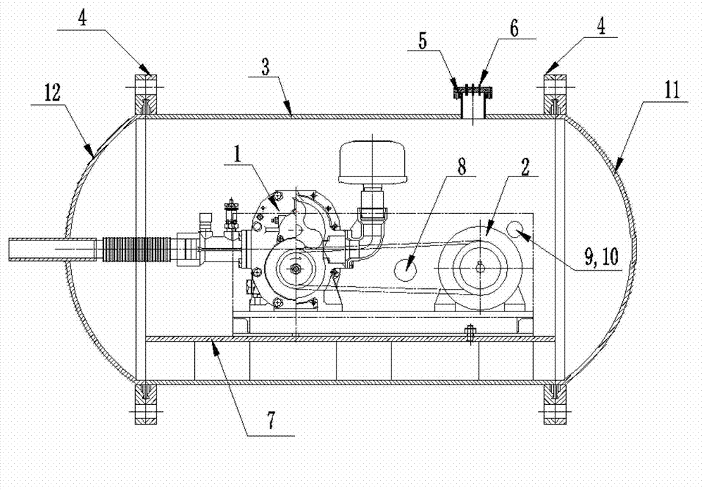
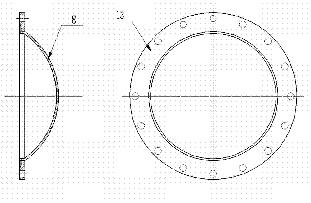
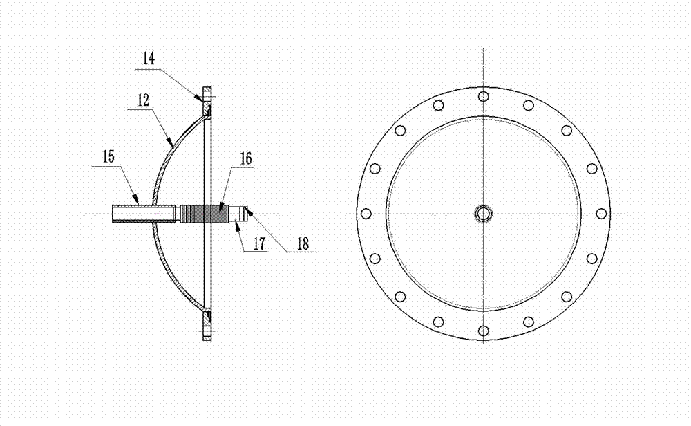
[0016] Such as Figure 1~3 As shown, when the pressure in the pipeline is lower than 3MPa, the fan 1 and the motor 2 are placed in the fan cover 3, and the fan support base 7 is welded in the fan cover 3, and the fan 1 and the motor 2 are fixed on the fan support base by bolts 7, the front end cover 11 of the fan cover and the rear end cover 12 of the fan cover are connected to the flange 4 of the fan cover through the flange 13 of the front cover of the fan cover and the flange 14 of the rear end cover of the fan cover, and rubber gaskets or Metal sealing gasket, each flange can use ordinary concave and convex flanges, the upper end of the fan cover 3 is connected to the lead flange 5, the lead flange is composed of two flanges, the upper flange acts as a seal, and the lower flange It plays the role of connection and sealing. The two flanges can be sealed with graphite or metal pads. The lead terminal 6 is welded on the upper flange of the lead flange 5. The main function of ...

Embodiment 2

[0019] Such as Figure 1~3 As shown, when the pressure in the pipeline is greater than 3MPa, the fan 1 and the motor 2 are placed in the fan cover 3, and the fan support base 7 is welded in the fan cover 3, and the fan 1 and the motor 2 are fixed on the fan support base 7 by bolts Above, the front end cover 11 of the fan cover and the rear end cover 12 of the fan cover are connected to the flange 4 of the fan cover through the flange 13 of the front cover of the fan cover and the flange 14 of the rear end cover of the fan cover. Rubber gaskets or metal gaskets are used between the connecting flanges. Gasket, each flange can use a knife-edge flange. The upper end of the fan cover 3 is connected with a lead flange 5. The lead flange is composed of two flanges. The upper flange acts as a seal, and the lower flange acts as a seal. Connection and sealing function, the two flanges are welded together, and the lead terminal 6 is welded on the upper flange of the lead flange 5. The ma...


PUM


Abstract

The invention provides a fan device driving gas to circulate in a high-temperature high-pressure sealed pipeline. A Root's or centrifugal fan and a motor are disposed in a fan hood. Two ends of the fan hood are connected with front and rear end covers of the fan through flanges. The fan hood is cylindrical. The front and rear end covers of the fan hood are pan-shaped. The front end cover of the fan hood is welded to an intake pipeline. The rear end cover of the fan hood is welded to a straight tube. The outer end of the straight tube is welded to an exhaust pipeline. The inner end of the straight tube is welded to a corrugated tube. The other connecting end of the corrugated tube is provided with two seal grooves, and O-shaped seal rings are disposed on the seal grooves. After the O-shaped seal rings are sleeved on the connecting end of the corrugated tube, the corrugated tube is inserted into an outlet of the fan directly. A lead flange is arranged at the upper end of the fan hood. Two water access tube joints are welded on two sides of the fan hood. Sufficient coolant is provided for the motor through the water access tube joints. Motive seal of the fan of the fan device is changed into static seal of the fan hood, so that sealing reliability can be guaranteed.

Description

technical field [0001] The invention relates to a novel fan device for driving gas circulation, in particular to a fan device for driving gas circulation in a high-temperature and high-pressure sealed pipeline. Background technique [0002] At present, the devices used to drive gas circulation in high-temperature and high-pressure sealed pipelines generally include piston compressors, diaphragm compressors, and specially designed Roots fans and centrifugal fans. [0003] Piston compressors and diaphragm compressors can be directly connected to pipelines when they are used to drive gas circulation devices in high-temperature and high-pressure sealed pipelines, but these two compressors have relatively strict requirements on the temperature of the inlet gas, which are generally lower than 50°C , when used in high-temperature and high-pressure sealed pipelines, the gas before the compressor inlet needs to be cooled, and the cooling capacity and stability of the cooler are requi...

Claims


Application Information

Patent Timeline
IPC IPC(8): F04D25/08F04C18/14
Inventor 李小龙朱志强吴宜灿黄群英
Owner HEFEI INSTITUTES OF PHYSICAL SCIENCE - CHINESE ACAD OF SCI
Why Eureka
Try Eureka