Check patentability & draft patents in minutes with Patsnap Eureka AI!

Transient waveform full voltage fault recording online detection device and working method thereof

A technology of fault recording and detection device, which is applied in the direction of using digital measurement technology for measurement, etc., can solve the problems of inability to detect transient voltage fault waves, harmonics, notch waves, flicker fault waves, etc. To achieve the effect of reasonable structure, convenient use and no influence

Inactive Publication Date: 2013-04-17
ANHUI ONESKY ELECTRIC TECH
View PDF5 Cites 3 Cited by
  • Summary
  • Abstract
  • Description
  • Claims
  • Application Information

AI Technical Summary

Problems solved by technology

The overvoltage detector is composed of a signal collector and a controller electrically connected to a resistor divider. Although it can detect overvoltage, it also has shortcomings. First, the resistor divider inevitably has an inductance. It not only affects the waveform of the detected overvoltage, but also cannot fully and effectively detect the transient wave of the overvoltage, especially the high-frequency transient wave; secondly, the detection method is based on the premise of hardware triggering, so that it can only Detect transient voltage fault waves of overvoltage category, but cannot detect transient voltage fault waves of non-overvoltage category, such as harmonics, notches, flicker and other fault waves cannot be detected

Method used


Image

  • Transient waveform full voltage fault recording online detection device and working method thereof

Examples


Embodiment Construction

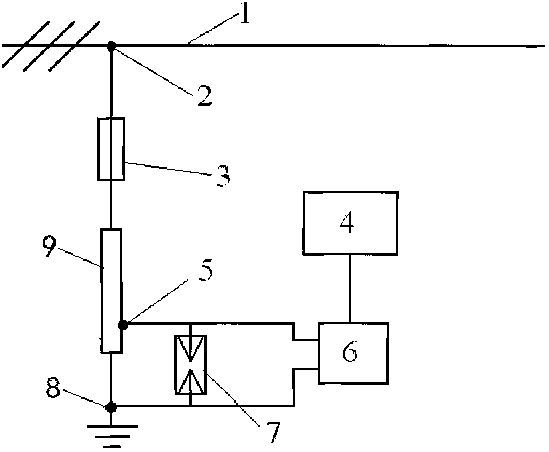
[0022] see figure 1 , the composition of the transient wave full-voltage fault recording online detection device is as follows: the non-inductive resistor divider 9 is equipped with a resistance ratio of 1000: 1 (can be between 1000~3000: 0.9~1.1, used to divide 10 ~ 35KV voltage division is ≤ 44V) Set the voltage division tap terminal 5, one end of the low resistance value after the tap is electrically connected to the ground terminal 8, and the other end is electrically connected to the high voltage terminal 2 through the non-inductive fuse 3; Wherein, the resistance value of the non-inductive resistor divider 9 is 10MΩ (can be between 10-35MΩ). A gas discharge tube 7 and a sampling card 6 with a sampling frequency ≥ 30 MHz / s are connected in parallel between the voltage divider tap terminal 5 and the ground terminal 8, and the output end of the sampling card 6 is electrically connected to the industrial controller 4; wherein, the gas discharge tube 7 The model of the sampl...


PUM

PropertyMeasurementUnit
Resistanceaaaaaaaaaa

Abstract

The invention discloses a transient waveform full voltage fault recording online detection device and a working method thereof. The transient waveform full voltage fault recording online detection device is characterized in that one end, which has a low resistance value after tapping, of a non-inductive resistance voltage divider (9) provided with a voltage tapping terminal (5) is electrically connected with a grounding terminal (8), and the other end of the non-inductive resistance voltage divider (9) is electrically connected with a high-voltage wiring terminal (2) through a non-inductive fuse wire (3); a gas discharge tube (7) and a sampling card (5) with the sampling frequency being more than or equal to 30MHz / s are connected between the voltage tapping terminal (5) and the grounding terminal (8) in parallel; and the output end of the sampling card (5) is electrically connected with an industrial controller (4). The working method disclosed by the invention comprises the following steps of: setting the sampling speed of the sampling card as 90-110ns / time, storing acquired voltage data in sequence, by taking the currently acquired voltage data as a starting point, respectively calculating change gradients of 9-11 returned voltage data, 1900-2100 returned voltage data and not more than 20ms of returned voltage data, and respectively considering the change gradients as waveforms in lightning stroke overvoltage, or switching overvoltage or non-overvoltage types according to gradient angles. The transient waveform full voltage fault recording online detection device can be used for detecting various transient voltage fault waves.

Description

technical field [0001] The invention relates to an on-line detection device and working method for fault recording, in particular to an on-line detection device and working method for transient wave full-voltage fault recording. Background technique [0002] In the power system, various overvoltages are very harmful to the equipment. In order to detect overvoltage, people often use overvoltage detection equipment, such as the overvoltage detector of the type GYC-2X currently being used in the system. The overvoltage detector is composed of a signal collector and a controller electrically connected to a resistor divider. Although it can detect overvoltage, it also has shortcomings. First, the resistor divider inevitably has an inductance. It not only affects the waveform of the detected overvoltage, but also cannot fully and effectively detect the transient wave of the overvoltage, especially the high-frequency transient wave; secondly, the detection method is based on the p...

Claims


Application Information

Patent Timeline
IPC IPC(8): G01R19/25
Inventor 芮骏余银钢
Owner ANHUI ONESKY ELECTRIC TECH
Features
  • R&D
  • Intellectual Property
  • Life Sciences
  • Materials
  • Tech Scout
  • Unparalleled Data Quality
  • Higher Quality Content
  • 60% Fewer Hallucinations
Learn More