residual current transformer

A residual current, transformer technology, applied in the direction of inductor, transformer/inductor core, transformer/inductor coil/winding/connection, etc., can solve the problem of asymmetric magnetic circuit, uneven distribution of secondary winding, false residual current, etc.

Active Publication Date: 2016-04-27
CHANGSHU SWITCHGEAR MFG CO LTD (FORMER CHANGSHU SWITCHGEAR PLANT)
View PDF6 Cites 0 Cited by
  • Summary
  • Abstract
  • Description
  • Claims
  • Application Information

AI Technical Summary

Problems solved by technology

[0003] (1) The position of the primary current-carrying conductor in the core window is not centered or the distance to each side is not the same, or the secondary winding is not evenly distributed on the core, which may cause the magnetic circuit to be asymmetrical, resulting in local saturation of the magnetic circuit , generating a false residual current in the secondary winding;

Method used


Image

  • residual current transformer
  • residual current transformer
  • residual current transformer

Examples


Embodiment

[0034] Embodiment: A residual current transformer, comprising: a magnetic core assembly 10, a coil assembly 12 and a shield assembly 14, the coil assembly 12 surrounds the outer surface of the rectangular magnetic core assembly 10, and the shield assembly 14 includes a balanced winding coil 11 and The shielding ring 13, the magnetic core assembly 10 and the coil assembly 12 are located in the shielding cavity of the shielding ring 13, and the balance winding coil 11 surrounds the outer surface of the shielding ring 13;

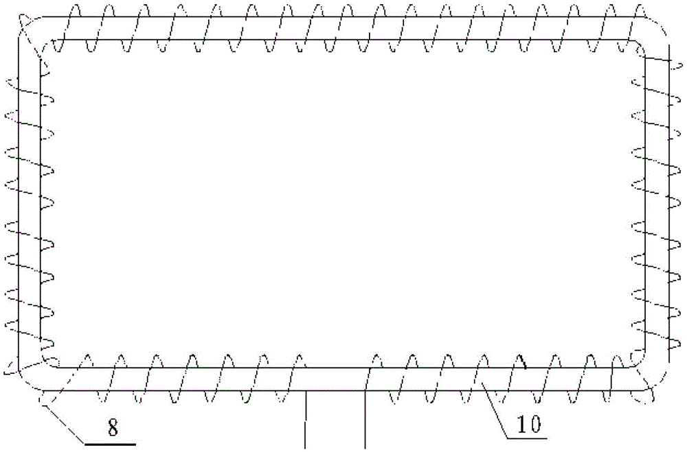
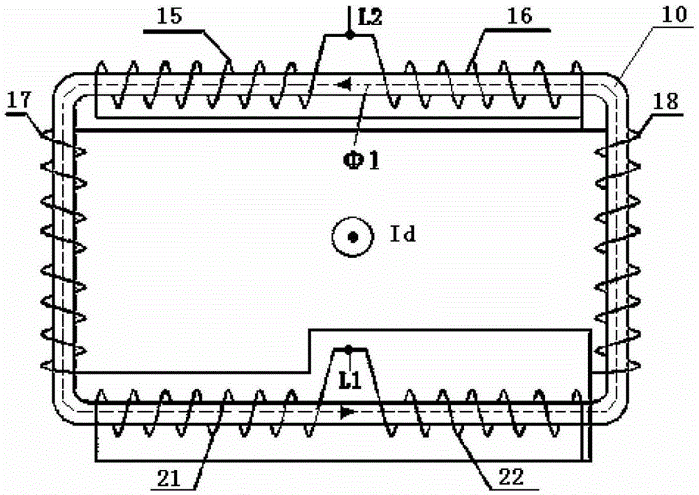
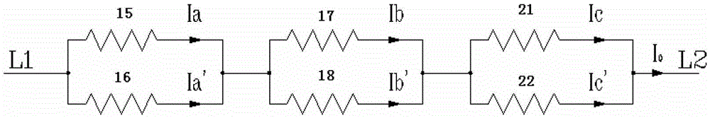
[0035]Described coil assembly 12 comprises test coil 9 and measuring coil 8, and this measuring coil 8 is positioned at the outside of test coil 9 and surrounds on the outer surface of magnetic core assembly 10, and measuring coil 8 is composed of the left sub-winding coil 15 wound along the first direction, The right sub-winding coil 16 wound along the second direction, two upper sub-winding coils 17 wound along the first direction and the second direction res...


PUM


Abstract

The invention discloses a residual current transformer which comprises a magnetic core component, a coil component and a shielding component. The coil component surrounds the outer surface of the rectangular magnetic core component and comprises a test coil and a measurement coil. The measurement coil is positioned outside the test coil, surrounds the outer surface of the magnetic core component and comprises a left winding coil, a right winding coil, two upper winding coils and two lower winding coils, wherein the left winding coil is wound along a first direction, the right winding coil is wound along a second direction, the two upper winding coils are wound along the first direction and the second direction respectively, and the two lower winding coils are wound along the first direction and the second direction respectively. The left winding coil and the right winding coil are in parallel connection and positioned between the two upper winding coils in parallel connection and the two lower winding coils in parallel connection. By the aid of the residual current transformer, saturation of the shielding component can be restrained, measurement errors are reduced, and reliability of a circuit breaker is improved.

Description

technical field [0001] The invention relates to the field of circuit breakers, in particular to a residual current transformer. Background technique [0002] At present, most common residual current transformers use ring-shaped bobbins and coils with uniform electromagnetic fields. Such residual current transformers are generally used in molded case circuit breakers with relatively small current specifications. For frame circuit breakers, due to the limited internal space, and considering factors such as high temperature rise of the busbar when operating high current, electrical insulation, and easy installation, the residual current transformer for frame circuit breakers is generally installed outside the circuit breaker and has a is a rectangle. The traditional residual current transformer is that the measuring coil is evenly wound on the magnetic core assembly, such as figure 1 shown. In this way, in actual work, due to the generation of false residual current, the cir...

Claims


Application Information

Patent Timeline
Patent Type & Authority Patents(China)
IPC IPC(8): H01F38/30H01F27/30H01F27/36H01F27/28H01F27/24
Inventor 殷建强邓国平金建达周龙明叶文杰
Owner CHANGSHU SWITCHGEAR MFG CO LTD (FORMER CHANGSHU SWITCHGEAR PLANT)
Why Eureka
Try Eureka