Drive circuit of synchronous rectification DC/DC (Direct Current/Direct Current) convertor

A technology of synchronous rectification and driving circuit, which is applied in the field of electronics to achieve the effect of reducing driving loss and improving power conversion efficiency

Active Publication Date: 2014-12-03
SOUTHEAST UNIV
View PDF5 Cites 0 Cited by
  • Summary
  • Abstract
  • Description
  • Claims
  • Application Information

AI Technical Summary

Problems solved by technology

Therefore, the current-driven synchronous rectifier has versatility, but it must be added with a current detection device and an auxiliary circuit

Method used


Image

  • Drive circuit of synchronous rectification DC/DC (Direct Current/Direct Current) convertor
  • Drive circuit of synchronous rectification DC/DC (Direct Current/Direct Current) convertor
  • Drive circuit of synchronous rectification DC/DC (Direct Current/Direct Current) convertor

Examples


Embodiment Construction

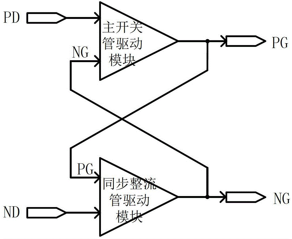
[0018] Such as figure 1 , the drive circuit of the present invention includes a main switch tube drive module and a synchronous rectifier drive module, the drive circuit and Figure 4 The switching stages shown include a main switch tube, a synchronous rectifier tube, a PWM controller, an inductor L, a capacitor C, and a resistor R to form a synchronous rectification DC / DC converter. The output signal PG of the main switch tube drive module is connected to the gate of the main switch tube MP0 and connected to an input terminal of the synchronous rectifier tube drive module, and one input terminal of the main switch tube drive module is connected to the PD signal output terminal of the PWM controller, synchronously The output signal NG of the rectifier drive module is connected to the gate of the synchronous rectifier MN0 and connected to the other input terminal of the main switching tube drive module, and the other input terminal of the synchronous rectifier drive module is c...


PUM


Abstract

The invention relates to a drive circuit of a synchronous rectification DC / DC (Direct Current / Direct Current) convertor. The drive circuit and a switch level commonly form the synchronous rectification DC / DC convertor, wherein the switch level comprises a main switch tube, a synchronous rectifier tube, a PWM (Pulse-Width Modulation) controller, an inductance L, a capacitance C and a resistance R; the drive circuit comprises a main switch tube drive module and a synchronous rectifier tube drive module; an output signal PG of the main switch tube drive module is connected with a grid electrode of the main switch tube, and is connected to one input end of the synchronous rectifier tube drive module; one input end of the main switch tube drive module is connected with a PD signal output end of the PWM controller; an output signal NG of the synchronous rectifier tube drive module is connected with a grid electrode of the synchronous rectifier tube and is connected to the other input end of the main switch tube drive module; and the other input end of the synchronous rectifier tube drive module is connected with an ND signal output end of the PWM controller.

Description

technical field [0001] The invention relates to a driving circuit of a synchronous rectification DC / DC converter, which belongs to the field of electronic technology. Background technique [0002] The low power consumption and high efficiency of power management chips have increasingly become an important indicator of circuit system design. For low-voltage circuits, synchronous rectification technology can improve power conversion efficiency, and the core issue of synchronous rectification technology is the drive of synchronous rectifier tubes. question. There are two types of driving methods for synchronous rectifiers: externally driven synchronous rectification and self-driven synchronous rectification. Among them, self-driven synchronous rectification is divided into voltage-driven synchronous rectification and current-driven synchronous rectification. [0003] The gate drive voltage of the externally driven synchronous rectifier needs to be obtained from an additional ...

Claims


Application Information

Patent Timeline
Patent Type & Authority Patents(China)
IPC IPC(8): H02M3/155H02M1/08
Inventor 徐申杨淼高庆苏军孙伟锋陆生礼时龙兴
Owner SOUTHEAST UNIV
Why Eureka
Try Eureka