Forming mould for self drilling screws

A technology for forming molds and screw drills, applied in the field of mold manufacturing, can solve the problems of inability to meet production requirements, loose fixing screws, poor stability, etc., and achieve the effects of convenient production and use, reliable and stable structure, and not easy to wear.

Inactive Publication Date: 2013-04-24
TAICANG SHOUYE AUTOMATIC CONTROL
View PDF7 Cites 3 Cited by
  • Summary
  • Abstract
  • Description
  • Claims
  • Application Information

AI Technical Summary

Problems solved by technology

However, during the operation of this drilling screw forming mold, the continuous impact of the mold core will cause the fixing screws to loosen or wear, resulting in loosening of the mold core and poor stability, which cannot meet the production needs

Method used


Image

  • Forming mould for self drilling screws
  • Forming mould for self drilling screws
  • Forming mould for self drilling screws

Examples


Embodiment Construction

[0036] For the purpose of full disclosure, the present invention will be further described in detail below in conjunction with the accompanying drawings and embodiments. It should be understood that the specific embodiments described below are only used to explain the present invention, and are not used to limit the protection scope of the present invention.

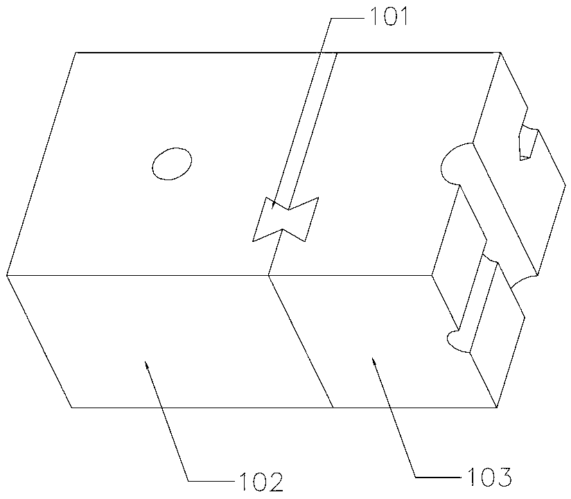
[0037] figure 1 and figure 2 The first embodiment of the auger tail forming mold of the present invention is shown. Such as figure 1 As shown, the screw drill tail forming mold includes a first body 102 and a second body 103 , and the first body 102 and the second body 103 are connected by a joint 101 .

[0038] The first body 102 can be made of high speed steel, and the second body 103 can be made of tungsten steel. In order to meet some higher processing pressure requirements, the second body 103 can also be welded to the second body 102 to increase the strength of the mold.

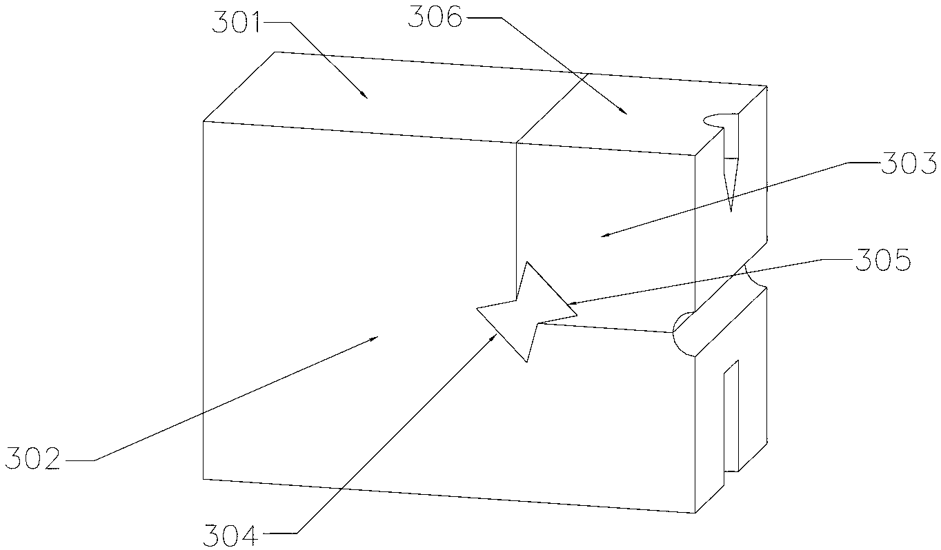
[0039] figure 2 It is an exploded ...


PUM


Abstract

The invention discloses a forming mould for self drilling screws. The forming mould comprises a first body and a second body, the first body is connected with the second body through a connector, a mould cavity is arranged on the second body, and material hardnesss of the first body is less than that of the second body. A first embedding groove is arranged at a first combination end of the first body, a second embedding groove is arranged at a second combination end of the second body, a first clamping portion and a second clamping portion are arranged on the connector, the first clamping portion and the second clamping portion are respectively matched with the first embedding groove and the second embedding groove, and the first clamping portion is connected with the second clamping portion through a center portion. Preferentially, the first embedding groove and the second embedding are respectively arranged on lower middle portions of the first body and the second body. By the aid of the forming mould, deformation of a mosaic structure caused by press mould impact force can be effectively avoided, and the forming mould is not easy to wear under transverse press mould impact force.

Description

technical field [0001] The invention relates to the field of mold manufacturing, in particular to an auger tail forming mold made of two materials with different hardness. Background technique [0002] The forming of the drill tail screw is roughly divided into two parts. One part is processed by a tooth rubbing machine to rub the thread, and the tail part is molded by a special processing mold. The forming of the drill tail part is that the end of the drill tail screw is two symmetrical. Molding mold compression molding. Most of the molding dies used in the production of screw drill tails are made of the same material cemented carbide, so its economic cost is relatively high. [0003] In the prior art, in order to reduce the cost, there is also a method of processing the mold base body and the drill tail forming part with different materials, and then combining them. Such as Chinese utility model patent specification CN201132191Y discloses a kind of mold for drill tail fo...

Claims


Application Information

Patent Timeline
Patent Type & Authority Applications(China)
IPC IPC(8): B21D37/10B21D37/01
Inventor 侯金麟
Owner TAICANG SHOUYE AUTOMATIC CONTROL
Why Eureka
Try Eureka