Roll change templates of straightening machine and roll change positioning method

A positioning method and technology for straightening rolls, applied in the field of metallurgy, can solve the problems of spline tooth collision, misalignment, damage, etc., to reduce roll change time, improve work efficiency, and simplify the roll change preparation process.

Active Publication Date: 2013-04-24
CISDI ENG CO LTD
View PDF7 Cites 4 Cited by
  • Summary
  • Abstract
  • Description
  • Claims
  • Application Information

AI Technical Summary

Problems solved by technology

[0004] The traditional roll changing and positioning method requires cumbersome operations such as table look-up or calculation. At the same time, there are various combinations of roll diameters for the straightening rolls and backup rolls. Mistakes may occur if you are not careful, resulting in external warps at the drive end of the straightening rolls. The key is not concentric with the internal spline on the spline sleeve, when the new straightening roller is pushed into the frame, it will cause the spline teeth to collide with each other and be damaged

Method used


Image

  • Roll change templates of straightening machine and roll change positioning method
  • Roll change templates of straightening machine and roll change positioning method
  • Roll change templates of straightening machine and roll change positioning method

Examples


Embodiment Construction

[0015] The preferred embodiments of the present invention will be described in detail below with reference to the accompanying drawings.

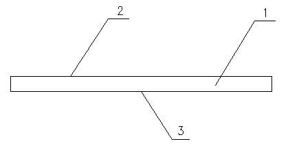
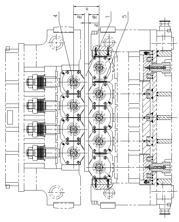
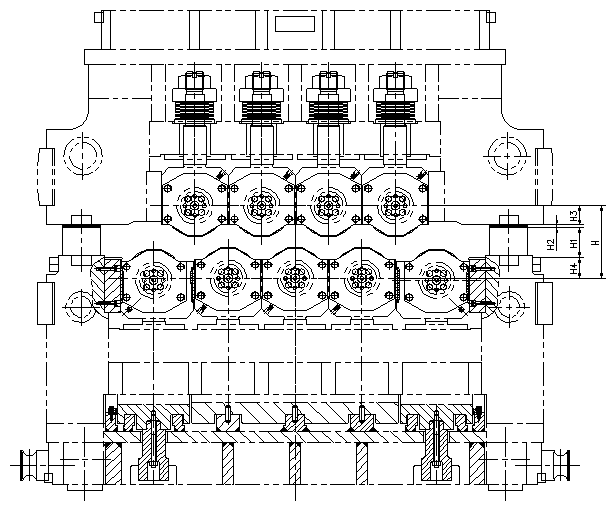
[0016] figure 2 It is a schematic diagram of the installation and positioning of the present invention. As shown in the figure, a method for positioning a roll changer of a straightening machine according to the present invention is to place the two roll changing templates 1 on both sides of the straightening machine (the transmission side and the operating side) respectively. Between the upper straightening roller bearing seat 4 and the lower straightening roller bearing seat 5, the upper straightening roller bearing seat 4 is pressed against the lower straightening roller bearing seat 5 through the roll changing template 1, and the thickness of the template main body 1 is selected Hc=L-Ha-Hb, the center distance L between the upper straightening roller bearing housing 4 and the lower straightening roller bearing housing 5 is the center d...


PUM


Abstract

The invention relates to roll change templates of straightening machine and a roll change positioning method. The two roll change templates are strip-shaped; the top surfaces of the roll change templates are parallel to the bottom surfaces of the roll change templates; the two roll change templates are arranged between an upper straightening roll bearing seat and a lower straightening roll bearing seat on the two sides of the straightening machine respectively; the upper straightening roll bearing seat is pressed on the lower straightening roll bearing seat through the roll change templates; and the sum of the central height of the upper straightening roll bearing seat, the central height of the lower straightening roll bearing seat and the thicknesses of the roll change templates is equal to the central distance between an upper straightening roll and a lower straightening roll. Even if the roll diameters of the straightening rolls and support rolls are changed by different combinations, the thicknesses of the roll change templates are still not changed, so that the influence on the central distance between the upper straightening roll and the lower straightening roll due to the combined change of the roll diameters of the straightening rolls and the support rolls is avoided, the roll change preparation process of the roll type straightening machine is simplified, the roll change time is shortened, the tooth contact risk in the roll change process is lowered, and the working efficiency is improved.

Description

technical field [0001] The invention relates to the field of metallurgy, in particular to a roll changing template and a roll changing positioning method for a straightening machine. Background technique [0002] Roller straightening machine is an important equipment in rolling steel production. After the roller leveling machine is used for a period of time, it is necessary to replace the straightening rollers in the straightening machine. When the upper straightening roller is changed, it is necessary to drop the upper straightening roller system onto the lower straightening roller system and push it out of the frame as a whole, and the spline sleeve at the driving end of the straightening roller is clamped by the clamping device. The center distance between the sleeve and the splined sleeve of the lower straightening roller is a constant value L. In the preparation process before the roll change, both the old roll system and the new roll system must ensure the center dist...

Claims


Application Information

Patent Timeline
Patent Type & Authority Applications(China)
IPC IPC(8): B23P19/00
Inventor 王勇蒋周强李宏图
Owner CISDI ENG CO LTD
Why Eureka
Try Eureka