

Puller with assembly type crossbeam
A prefabricated, cross-beam technology, applied in the field of pullers for dismantling parts, can solve the problems of complex processing technology, limited application scope, low matching accuracy, etc., and achieve the effects of high matching accuracy, wide application range and reliable connection.
- Summary
- Abstract
- Description
- Claims
- Application Information
AI Technical Summary
Problems solved by technology
Method used
Image

Examples
specific Embodiment approach 1
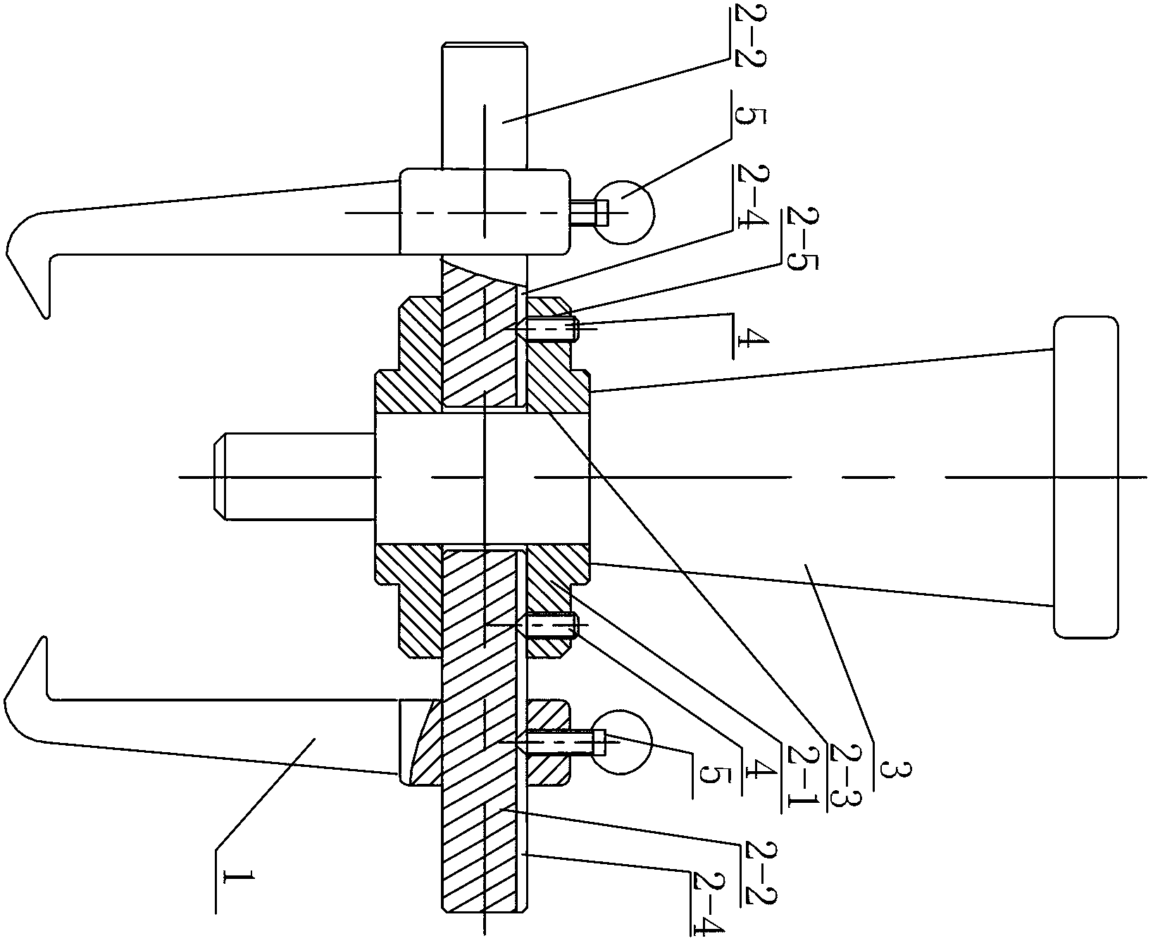
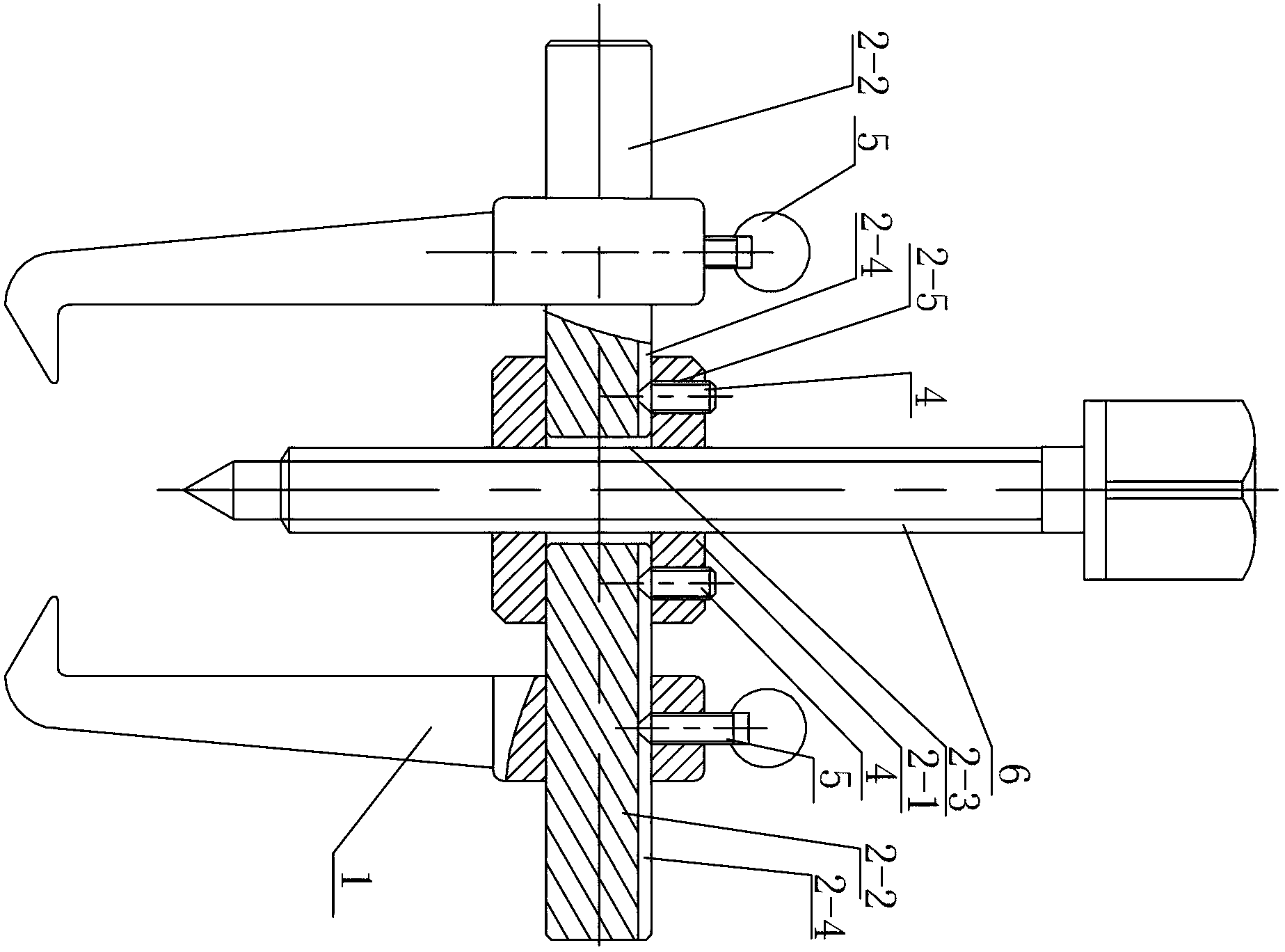
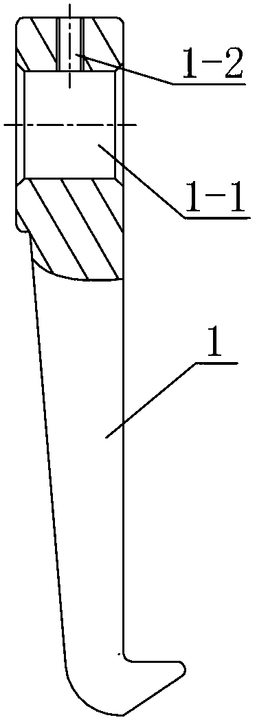
[0010] Specific implementation mode one: combine Figure 1-Figure 6 Describe this embodiment, a puller with an assembled beam in this embodiment includes a beam, a jack 3 or a lead screw 6, two pull claws 1 and two second fasteners 5, each pull claw 1 is The tail portion of the pull claw 1 is provided with a circular through hole 1-1 along the thickness direction of the pull claw 1, and the tail end face of each pull claw 1 is provided with a second central threaded through hole 1-2 communicating with the circular through hole 1-1, The tool also includes two first fasteners 4, the crossbeam includes a column 2-1 and two connecting shafts 2-2, and the middle part of the column 2-1 is provided with a first central screw thread along its height direction. The hole 2-3, the jack 3 or the lead screw 6 is threadedly connected with the first central threaded through hole 2-3 of the cylinder 2-1, and two connecting shafts 2 are perforated radially on the side wall of the cylinder 2-1 ...
specific Embodiment approach 2
[0011] Specific implementation mode two: combination figure 1 , figure 2 with Figure 5 To illustrate this embodiment, the end surface of the cylinder 2-1 in this embodiment is provided with two third threaded through holes 2-5 opposite to its axial direction, and the two connecting shafts 2-2 pass through the cylinder 2-1. The two third threaded holes 2-5 are threadedly connected, and the two connecting shafts 2-2 respectively abut against the two first fasteners 4 in the positioning grooves 2-4 to realize detachable connection. With such a setting, the connection is simple, convenient and reliable. Others are the same as in the first embodiment.
specific Embodiment approach 3
[0012] Specific implementation mode three: combination figure 1 with figure 2 This embodiment will be described. The second fastener 5 in this embodiment is a top wire. With such arrangement, the connection form is reliable and simple, the installation and disassembly are convenient, and the actual needs are met. Others are the same as in the first embodiment.
PUM
| Property | Measurement | Unit |
|---|---|---|
| Aperture | aaaaa | aaaaa |
Abstract
Description
Claims
Application Information