Die-cutting roller limiting block

A technology of limit block and die-cutting roller, which is applied in metal processing and other directions, can solve the problems of left-right movement, low precision, and easy deviation in the left-right direction, so as to ensure the accuracy of die-cutting, prevent deviation and ensure precision. Effect

Inactive Publication Date: 2013-04-24
坂崎雕刻模具(昆山)有限公司
View PDF4 Cites 0 Cited by
  • Summary
  • Abstract
  • Description
  • Claims
  • Application Information

AI Technical Summary

Problems solved by technology

[0003] Die-cutting rollers are mainly used in die-cutting processing of tobacco packaging, electronic product lamination, napkins, sanitary napkins, plastic products, leather products, aluminum foil paper, etc. The upper and lower rollers of the die-cutting rollers tend to deviate in the left and right directions during high-speed operation , easy to move left and right, low precision, affecting die-cutting quality

Method used


Image

  • Die-cutting roller limiting block
  • Die-cutting roller limiting block
  • Die-cutting roller limiting block

Examples


Embodiment Construction

[0016] The present invention will be further described below in conjunction with the accompanying drawings and specific embodiments.

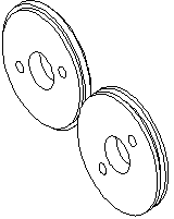
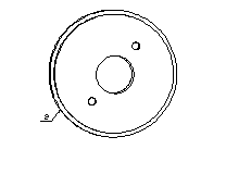
[0017] according to Figure 1-3 , Die-cutting roller limit block, characterized in that it includes concentric concave block 1 and convex block 2, the above two blocks are respectively installed on the operation surface side of the upper and lower die-cutting rollers, and the end faces of concave block 1 and convex block 2 are mutually meshing ( figure 1 ). Concave block and protruding block refer to that the end surface of the circumference is inwardly recessed or outwardly protruding, rather than the center of the circle being inwardly recessed or outwardly protruding. The cross section of the concave block 1 and the convex block 2 is circular, and the center of the concave block 1 and the convex block 2 is provided with a mounting hole ( figure 2 and image 3 ), the concave block 1 and the convex block 2 are fixed on the operating surfa...


PUM


Abstract

The invention belongs to the field of carving dies and particularly relates to a die-cutting roller limiting block. The die-cutting roller limiting block is characterized by comprising a concave block and a convex block which are concentric, the concave block and the convex block are mounted on operating face sides of an upper die-cutting roller and a lower die-cutting roller respectively, the end face sides of the concave block and the convex block are meshed with each other for limiting, the sections of the concave block and the convex block are round, mounting holes are arranged at the centers of the concave block and the convex block, and the concave block and the convex block are fixed to the operating face sides of the upper roller and the lower roller through the mounting holes. Die-cutting precision is guaranteed by adding the limiting block to prevent bilateral play of the upper roller and the lower roller during die cutting; and the limiting block includes the concave block and the convex block which are mounted on the operating face sides of the upper roller and the lower roller, requirements on the concentricity and the lateral finish of the upper roller and the lower roller are high, and bilateral precision of the upper roller and the lower roller during operation is guaranteed by means of vertical meshing of the concave block and the convex block, so that deviation is prevented.

Description

technical field [0001] The invention belongs to the field of engraving moulds, in particular to a limiting block for die-cutting rollers. [0002] Background technique [0003] Die-cutting rollers are mainly used in die-cutting processing of tobacco packaging, electronic product lamination, napkins, sanitary napkins, plastic products, leather products, aluminum foil paper, etc. The upper and lower rollers of the die-cutting rollers tend to deviate in the left and right directions during high-speed operation , easy to move left and right, low precision, affecting die-cutting quality. [0004] Contents of the invention [0005] The purpose of the present invention is to overcome the above-mentioned problems, and provide a limit block for die-cutting rollers that prevents the upper and lower rollers from moving left and right, and ensures the precision and quality of die-cutting. [0006] In order to achieve the above object, the technical solution adopted in the present i...

Claims


Application Information

Patent Timeline
IPC IPC(8): B26D7/26B26F1/42
Inventor 黄榕
Owner 坂崎雕刻模具(昆山)有限公司
Why Eureka
Try Eureka