Conveyor belt for metal workpieces

A technology for metal workpieces and conveyor belts, which is applied in the field of conveyor belts and can solve problems such as instability of metal workpieces

Inactive Publication Date: 2013-04-24
黄维明
View PDF9 Cites 10 Cited by
  • Summary
  • Abstract
  • Description
  • Claims
  • Application Information

AI Technical Summary

Problems solved by technology

[0003] The present invention intends to provide a conveyor belt for metal workpieces to solve the problem...

Method used


Image

  • Conveyor belt for metal workpieces
  • Conveyor belt for metal workpieces
  • Conveyor belt for metal workpieces

Examples


Embodiment Construction

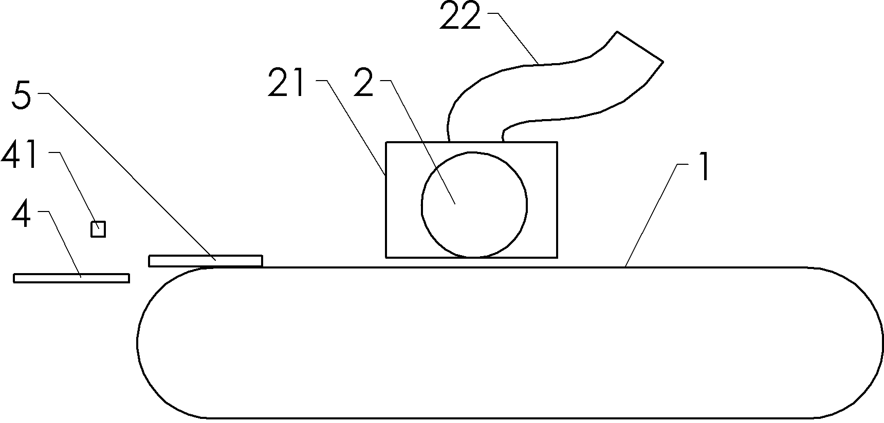
[0022] Take the blade grinding treatment of kitchen knives as an example, such as figure 1 As shown: it includes a conveyor belt body 1 including a frame and a magnetic body, a grinding wheel 2 arranged above the belt body, a dust cover 21 is arranged around the grinding wheel, and a negative pressure dust suction pipe 22 is connected to the dust cover. The negative pressure suction pipe is connected with an exhaust fan.

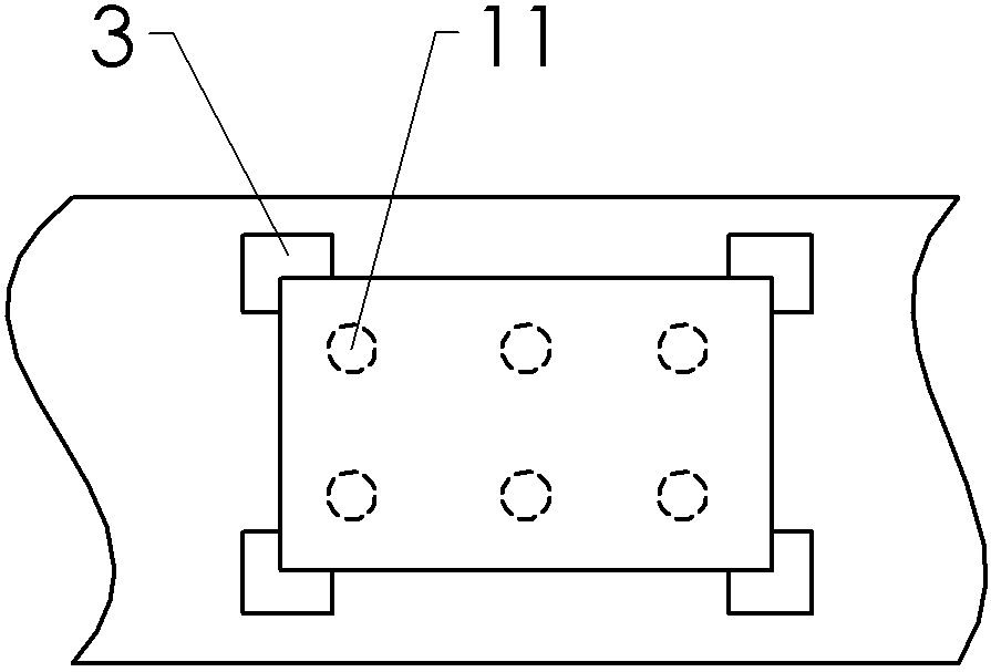
[0023] Such as figure 2 Shown: the belt body is provided with four L-shaped positioning blocks 3 to prepare for the position of the fixed blade, and each blade position on the belt body is provided with six strong magnets 11.

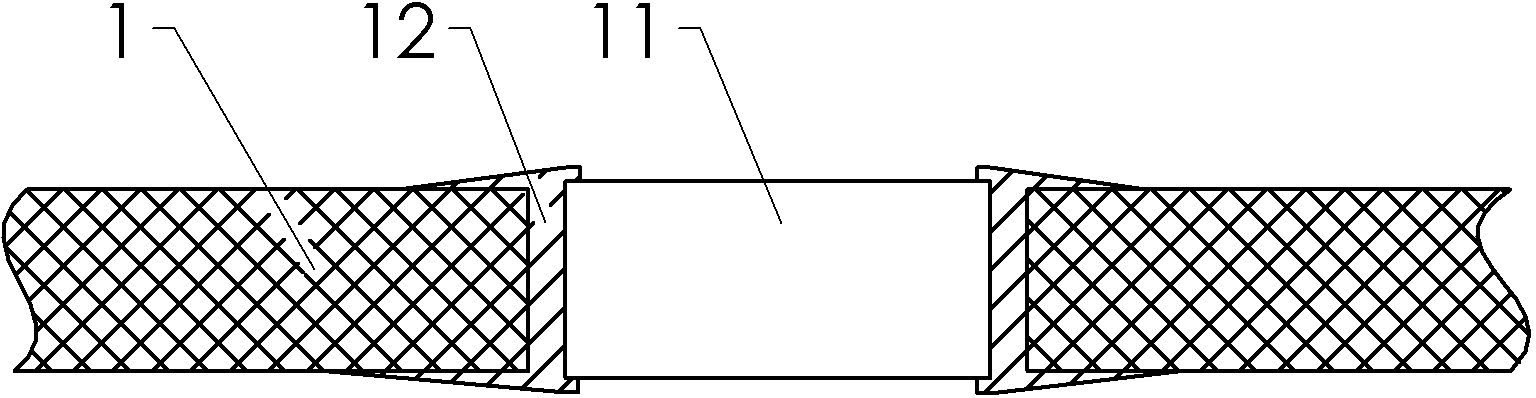
[0024] Such as image 3 As shown: the belt body is provided with a fixing hole, the ring-shaped magnet fixing part 12 is riveted in the fixing hole, and the columnar strong magnet 11 is clamped in the magnet fixing part.

[0025] Such as figure 1 As shown: the discharge end of the belt body is provided with a discharge pallet 4 t...


PUM


Abstract

The invention provides a conveyor belt for metal workpieces and solves the problem that metal workpieces on the conveyor belt are instable under the effect of external force in the prior art. The conveyor belt for metal workpieces comprises a movable belt body and is characterized in that magnets, which can be permanent magnets or electromagnetism generators, are arranged on the belt body. The magnets operate to generate magnetic field firmly adsorbing the metal workpieces on the conveyor belt so as to guarantee positional stability of the metal workpieces.

Description

technical field [0001] The present invention relates to a conveyor belt. Background technique [0002] Conveyor belt is a typical means of transportation, often used in the transfer of metal workpieces in the assembly line. However, the conveyor belt inevitably shakes during operation, or the metal workpiece is milled and forged due to processing needs. How to ensure the stability of the metal workpiece on the conveyor belt is a problem that people are trying to solve. Contents of the invention [0003] The present invention intends to provide a conveyor belt for metal workpieces to solve the problem in the prior art that the metal workpieces on the conveyor belt are unstable under the action of external force. [0004] The conveyor belt used for metal workpieces in this solution includes a movable belt body, and is characterized in that: the belt body is provided with a magnetic body. [0005] The magnetic body can be a permanent magnet or an electromagnetic generating ...

Claims


Application Information

Patent Timeline
IPC IPC(8): B65G15/58B65G47/34B24B19/00B24B55/06
Inventor 黄维明
Owner 黄维明
Why Eureka
Try Eureka