High-depth winze shaft blocking state observation monitoring method

A monitoring method and technology of sliding wells, which are used in wellbore/well components, measurement, earth-moving drilling and mining, etc., can solve the problems of inability to protect the personal safety of operators, affecting mine production, and blocking the connection between the sliding well and the contact road, etc. Achieve the effect of avoiding personal injury accidents and eliminating hidden dangers in production

Active Publication Date: 2013-04-24
JIUQUAN IRON & STEEL GRP
View PDF4 Cites 4 Cited by
  • Summary
  • Abstract
  • Description
  • Claims
  • Application Information

AI Technical Summary

Problems solved by technology

However, during the production process, accidents such as blockage and landslides often occur in high and deep shafts, which seriously affect mine production and pose a great threat to personal safety.
[0003] Generally, the blockage of the chute is observed through the chute, but due to the existence of side pressure when the ore flows in the shaft during the ore drawing process, the connection between the chute and the chute is basically blocked, and the observation needs to be carried out after the ballast is cleared
However, since it is impossible to judge the clogging position of the chute in advance, it is difficult to estimate when the ore surface below the clogging arch in the shaft will be drawn to the floor of the communication channel. Put the ore surface inside to the floor of the connecting road to clear the ore clogging the connecting road, and then manually observe the blockage of the chute after cleaning the ore
In the whole process of ore drawing, manual detection, cleaning of ore slag and blockage observation, operators are directly exposed to the range of huge air shock wave damage once the blockage arch collapses, and the personal safety of the operators cannot be guaranteed.

Method used


Image

  • High-depth winze shaft blocking state observation monitoring method
  • High-depth winze shaft blocking state observation monitoring method
  • High-depth winze shaft blocking state observation monitoring method

Examples


Embodiment Construction

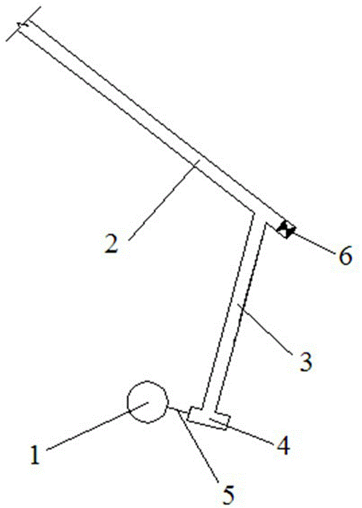
[0021] The present invention will be described in detail below in conjunction with the accompanying drawings and specific embodiments.

[0022] In the process of mine mining, high-deep chute is usually used to transport the mined raw ore, which has the advantages of less investment, less equipment, low cost and large production capacity. pose a great threat to personal safety. In order to find out the reasons of chute clogging and landslide and fundamentally eliminate production hidden dangers, it is necessary to observe and analyze the chute wellbore in order to formulate a scientific and reasonable chute maintenance plan.

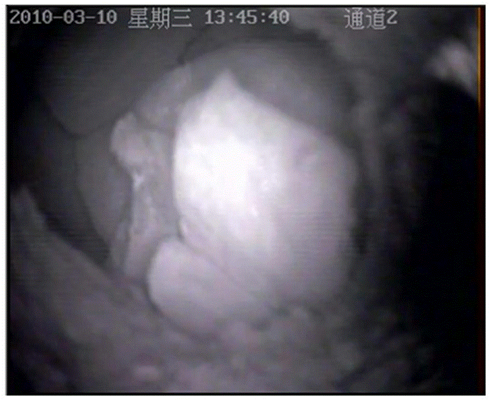
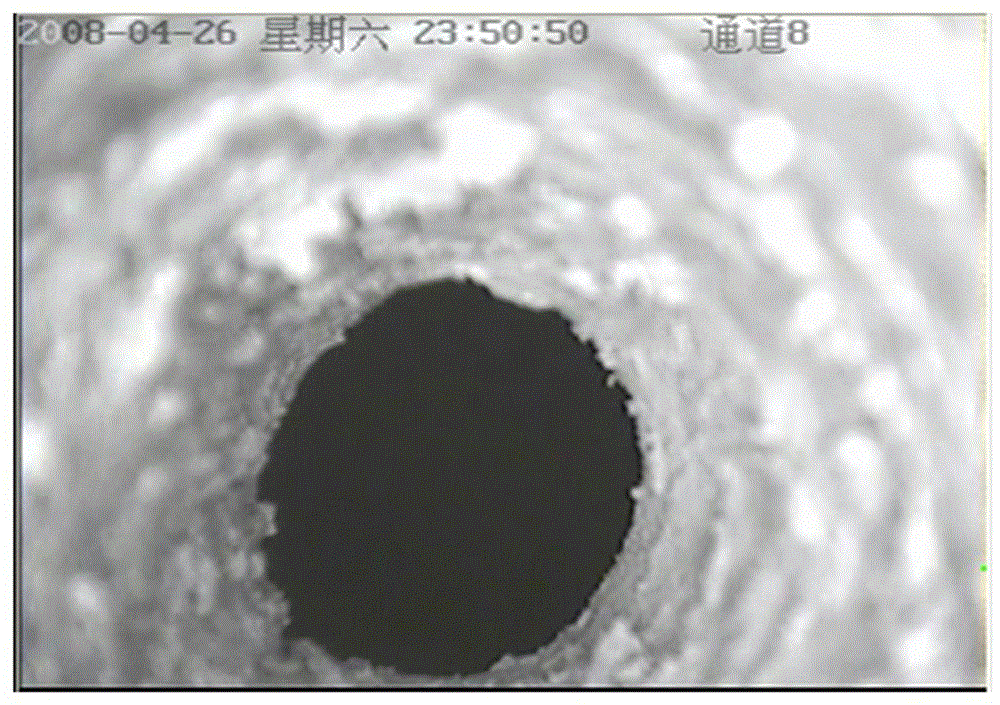
[0023] In general, the blockage of the high-deep chute is observed through the connection roadway, but due to the side pressure when the ore flows in the high-deep chute shaft during the ore-drawing process of the high-deep chute, the connection between the chute and the connection roadway is basically blocked, and it needs to be cleared observations can...


PUM


Abstract

The invention provides a high-depth winze shaft blocking state observation monitoring method. An observe cannon hole communicated with a high-depth winze is drilled, a flowing situation of ore in the high-depth winze when the ore is placed is observed through a voice and video frequency monitoring system after the high-depth winze is blocked, a vertical distance between a falling ore face and a central position of a cross position of the observe cannon hole and the high-depth winze, quantity of ore reserve is calculated, and the vertical distance between an ore face and the central position of the cross position of the observe cannon hole and the high-depth winze meets a setting distance requirements; a blocking position of the ore in the high-depth winze is measured; a blocking arc in a high-depth winze shaft is monitored, and stability degree of the blocking arc is judged. The high-depth winze shaft blocking state observation monitoring method provides scientific and reasonable basis for preparing a scheme to dredge the winze, and greatly improves safety work environment and labor strength of operating personnel and is accurate in ore placing control.

Description

technical field [0001] The invention belongs to the technical field of metallurgy and mines, and relates to a method for monitoring a high-depth chute, in particular to a method for observing and monitoring the blockage of a high-deep chute shaft. Background technique [0002] In the process of mining, the production mode of high-depth shaft transportation with the advantages of less investment, less equipment, low cost and large production capacity is usually adopted. However, during the production process, accidents such as blockage and landslides often occur in the high-depth chute, which seriously affect the mine production and pose a great threat to personal safety. [0003] In general, the blockage of the chute is observed through the chute, but due to the side pressure of the ore flowing in the shaft during the ore drawing process, the connection between the chute and the chute is basically blocked, and the observation needs to be cleared. However, since it is imposs...

Claims


Application Information

Patent Timeline
Patent Type & Authority Applications(China)
IPC IPC(8): E21B47/002E21B47/00
Inventor 陈永祺
Owner JIUQUAN IRON & STEEL GRP
Why Eureka
Try Eureka