
Lift-resistance type vertical-axis wind generator blade

A wind turbine, vertical axis technology, applied in wind turbines, wind turbines at right angles to the wind direction, motors, etc., can solve the problem of low blade tip speed ratio and wind energy conversion rate, high starting wind speed of blades, and low torque, which is difficult to start. and other problems, to achieve the effect of improving wind energy conversion rate, large torque, and high tip speed ratio

Inactive Publication Date: 2013-04-24
秦皇岛握石环保科技有限公司
View PDF0 Cites 0 Cited by
  • Summary
  • Abstract
  • Description
  • Claims
  • Application Information

AI Technical Summary

Problems solved by technology

[0002] Existing vertical axis wind turbine blades are mainly divided into two types: lift type and drag type. The lift type blade uses the pressure difference generated by the air flow on the blade to do work, and has a higher tip speed ratio and wind energy conversion rate. But the torque is small and it is difficult to start; the resistance type blade uses the resistance generated by the air flow on the blade to do work, has a large torque and good starting performance, but the tip speed ratio and wind energy conversion rate are low
Most of the lift-type blades disclosed in the prior art follow the design of the aeronautical airfoil, that is, the wing of an aircraft, which has the problems of high wind speed, low power and difficulty in starting the blades.

Method used


Image

  • Lift-resistance type vertical-axis wind generator blade
  • Lift-resistance type vertical-axis wind generator blade

Examples


Embodiment Construction

[0009] The specific embodiment of the present invention will be described with reference to the accompanying drawings.

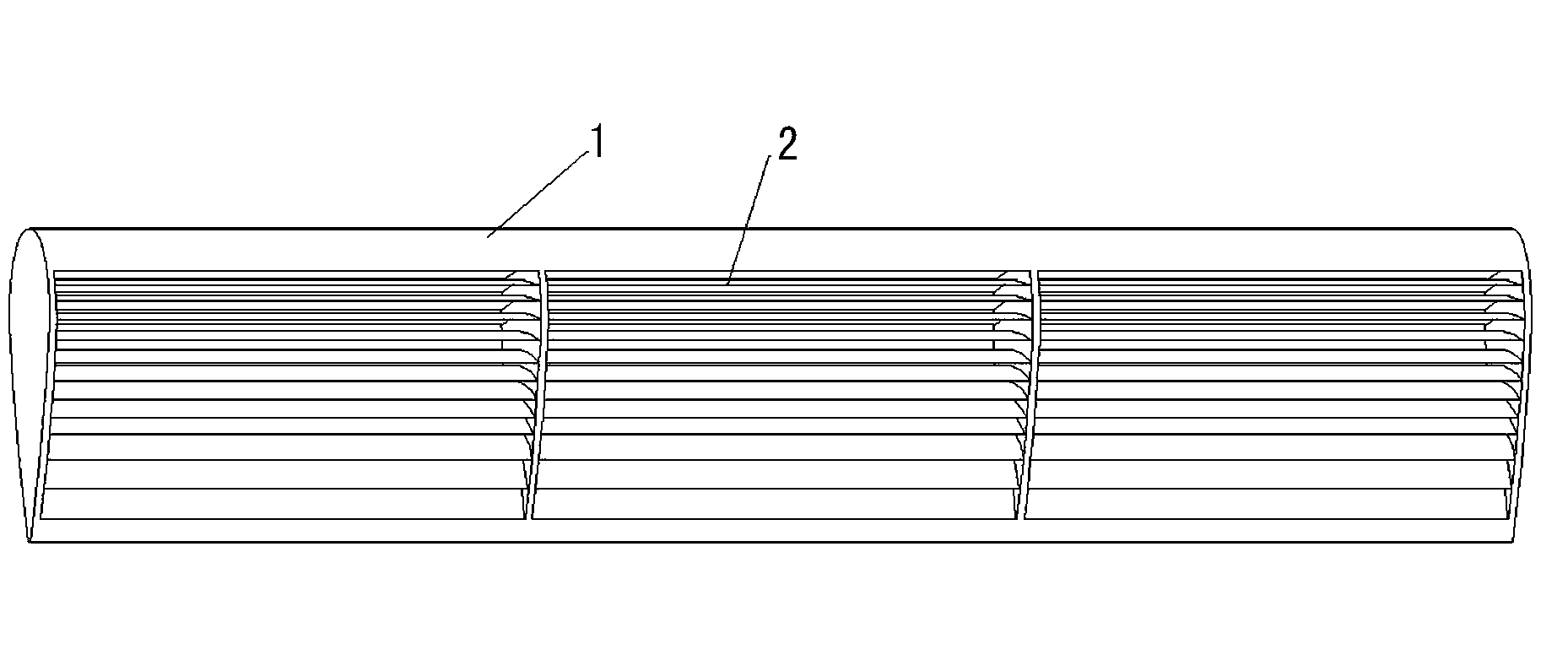
[0010] as attached figure 1 , the blade of the lift-drag type vertical axis wind power generator includes an airfoil blade 1, and the blade 1 is vertically installed. Airflow passages 2 are arranged on the cross section of the blade 1 , and the airflow passages 2 are arranged in multiple sections in the longitudinal direction of the blade 1 . The air flow passage 2 of the accompanying drawing embodiment is arranged in three sections.

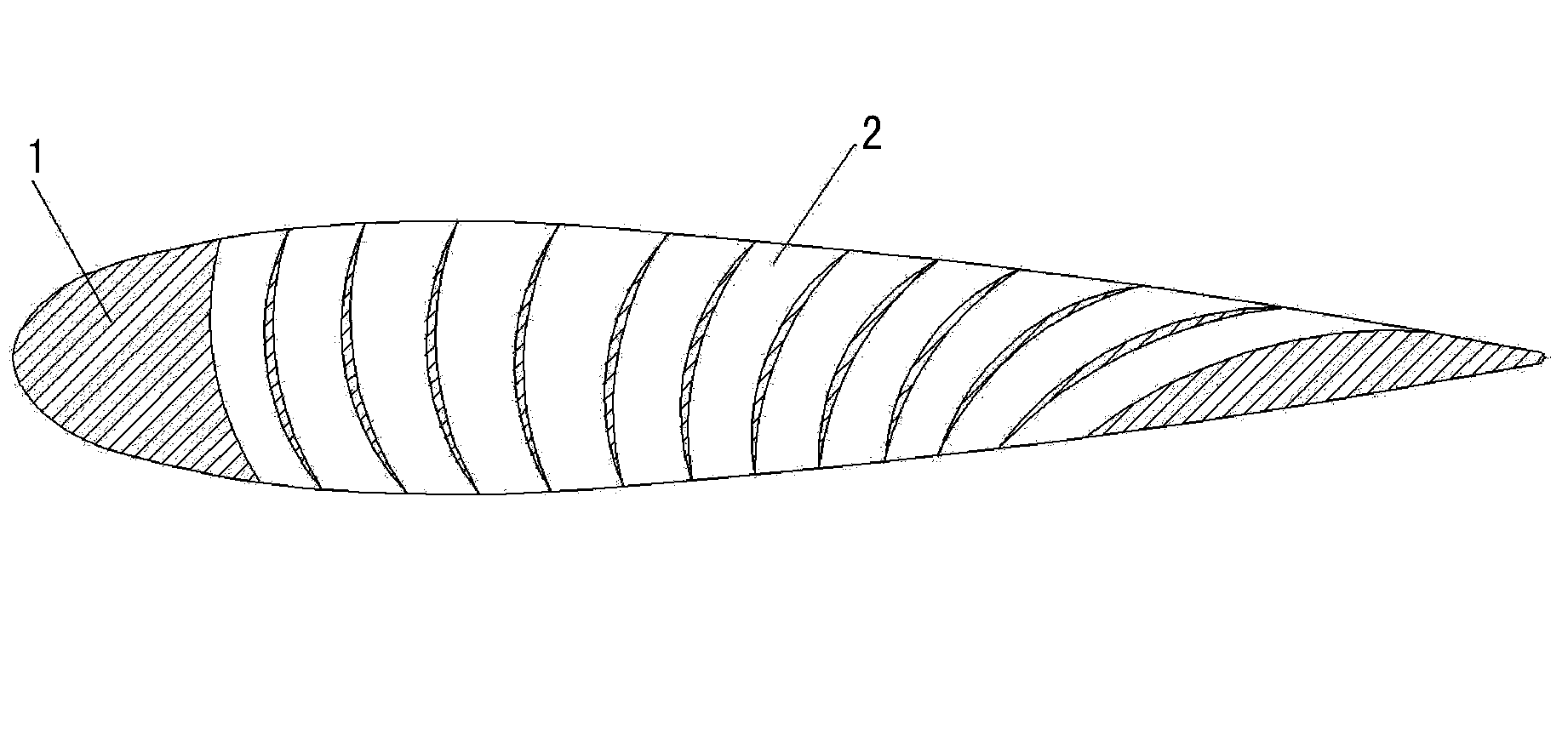
[0011] as attached figure 2 , the airflow channel 2 is arc-shaped in the transverse section of the blade, the channel opening of the airflow channel 2 is placed on both sides of the blade 1, the convex arc surface of the airflow channel 2 faces the leading edge of the blade 1, the airflow channel The concave arc surface of 2 faces the trailing edge of blade 1.

[0012] as attached figure 2 , when the present invention i...


PUM


Abstract

The invention discloses a lift-resistance type vertical-axis wind generator blade. The wind generator blade comprises a vertical wing-type blade, wherein an air duct with a transverse arc section is arranged on the blade; openings of the air duct are formed in two side surfaces of the blade, and the convex arc surface of the air duct faces the front edge of the blade while the concave arc surface of the air duct faces the back edge of the blade. According to the lift-resistance type vertical-axis wind generator blade, due to the arrangement of the arc-shaped air duct on the wing-type blade, airflow produces a pressure difference on the wing-type surface of the blade so as to do lift-type work and produces resistance in the arc-shaped air duct of the blade so as to do resistance-type work, so that the blade has the characteristics of a lift-type blade and a resistance-type blade and has large torque, high tip speed ratio and good starting performance. Meanwhile, the wind energy conversion rate of the blade is greatly improved through the superposition of the lift-type work and the resistance-type work.

Description

technical field [0001] The invention relates to a wind power generator, in particular to a lift-drag type vertical axis wind power generator blade. Background technique [0002] Existing vertical axis wind turbine blades are mainly divided into two types: lift type and drag type. The lift type blade uses the pressure difference generated by the air flow on the blade to do work, and has a higher tip speed ratio and wind energy conversion rate. But the torque is small and it is difficult to start; the resistance type blade uses the resistance generated by the air flow on the blade to do work, has a large torque and good starting performance, but the tip speed ratio and wind energy conversion rate are low. Most of the lift-type blades disclosed in the prior art follow the design of the aeronautical airfoil, that is, the wing of an aircraft, which has the problems of high wind speed, low power and difficulty in starting the blades. Contents of the invention [0003] The objec...

Claims


Application Information

Patent Timeline
IPC IPC(8): F03D3/06
CPCY02E10/74
Inventor 高维珠宋志军
Owner 秦皇岛握石环保科技有限公司
Learn More