Buffering and filtering device for air exhaust port of vacuum pump

A filter device and air suction port technology, which is applied to parts of pumping devices for elastic fluids, pump elements, rotary piston type/oscillating piston type pump parts, etc., can solve the problem of reducing service life, damaging rotary vanes, loading Object movement and other issues to achieve the effect of reducing force

Inactive Publication Date: 2013-04-24
ANHUI BENGBU HUAYI CONDUCTIVE FILM GLASS
View PDF7 Cites 2 Cited by
  • Summary
  • Abstract
  • Description
  • Claims
  • Application Information

AI Technical Summary

Problems solved by technology

[0003] But when the vacuum pump is turned on, the air is directly discharged from the vacuum chamber through the suction port. Due to the high pumping rate, the load in the vacuum chamber may move, or the load or dust will be drawn into the vacuum pump, which will damage the rotary vane and reduce the use of the pump. life

Method used


Image

  • Buffering and filtering device for air exhaust port of vacuum pump
  • Buffering and filtering device for air exhaust port of vacuum pump
  • Buffering and filtering device for air exhaust port of vacuum pump

Examples


Embodiment 1

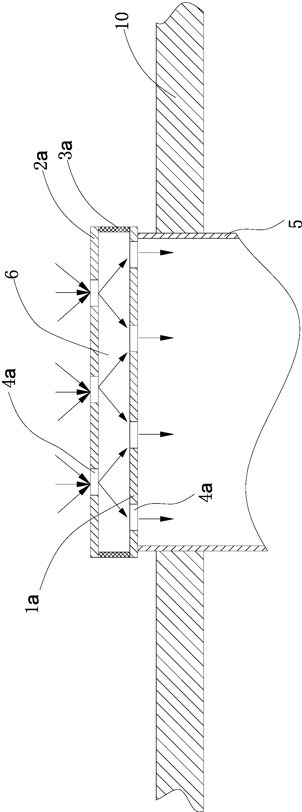
[0014] like figure 1 As shown, the buffer filter device for the suction port of the vacuum pump includes two baffles. A side wall 3a is welded between the edge of the first baffle 1a and the edge of the second baffle 2a. The area of ​​the first baffle 1a is larger than the cross section of the air suction port. The area of ​​a baffle plate 1a is equal to the area of ​​the second baffle plate 2a, the first baffle plate 1a and the second baffle plate 2a are parallel, and the first baffle plate 1a, the second baffle plate 2a and the side wall 3a form an airtight cylindrical space cavity 6, the area of ​​the first baffle plate 1a is greater than the radial cross-sectional area of ​​the vacuum pump air outlet 5, and the bottom of the first baffle plate 1a is welded to the upper end of the air outlet 5; Air holes 4a, seven air extraction holes 4a communicating with the outside world are respectively arranged on the second baffle plate 2a, the air extraction holes 4a of the first baf...

Embodiment 2

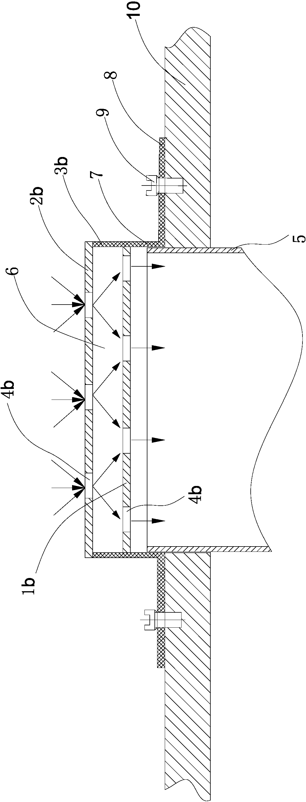
[0016] like figure 2 As shown, the buffer filter device at the suction port of the vacuum pump includes two baffles, a side wall 3b is welded between the edge of the first baffle 1b and the edge of the second baffle 2b, and the area of ​​the first baffle 1b is equal to that of the second baffle 2b Area, the first baffle plate 1b and the second baffle plate 2b are parallel, the first baffle plate 1b, the second baffle plate 2b and the side wall 3b form a closed cylindrical cavity 6, and the area of ​​the first baffle plate 1b is larger than the suction port of the vacuum pump 5 The radial cross-sectional area, the side wall 3b has an extension 7 in the axial direction of the air inlet 5 to the air outlet 5, so that the air outlet 5 is sleeved in the extension 7 of the side wall 3b, and the bottom of the extension 7 has a folded edge 8, through Bolts 9 make the flange 8 fixedly connected with the wall 10 of the vacuum chamber; the first baffle 1b has six air extraction holes 4b...

Embodiment 3

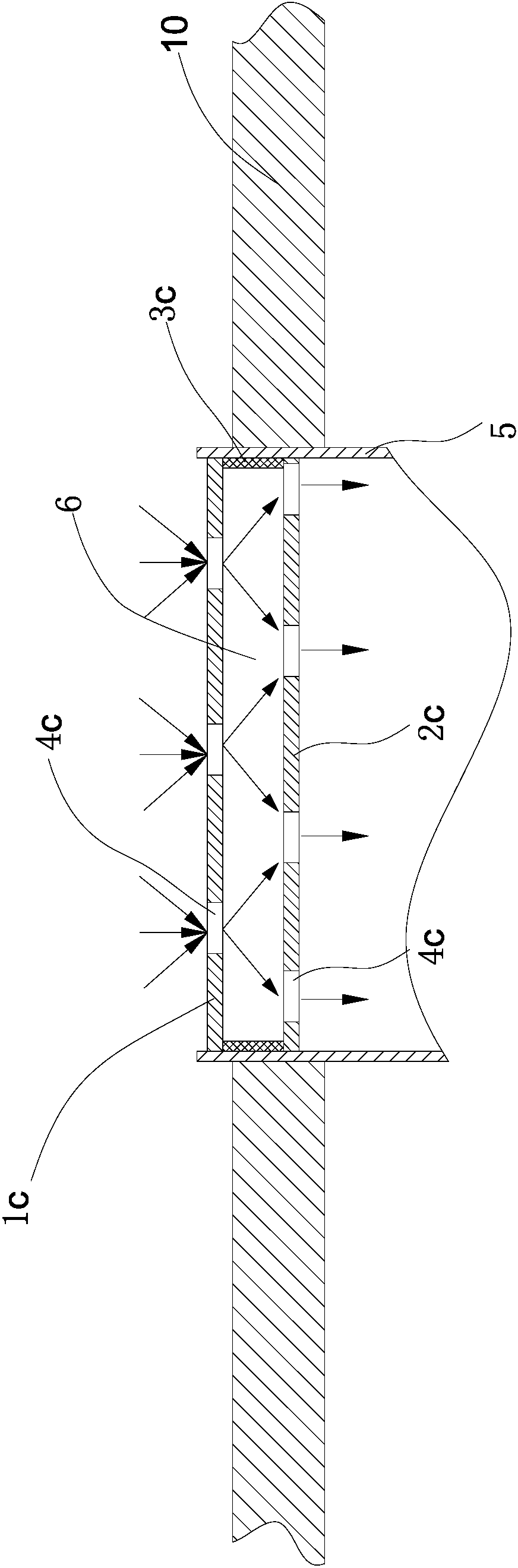
[0018] like image 3 As shown, the buffer filter device at the suction port of the vacuum pump includes two baffles. A side wall 3c is welded between the edge of the first baffle 1c and the edge of the second baffle 2c. The area of ​​the first baffle 1c is equal to the section of the suction port 5. The area of ​​the first baffle 1c is equal to the area of ​​the second baffle 2c, the first baffle 1c and the second baffle 2c are parallel, and the first baffle 1c, the second baffle 2c and the side wall 3c form a closed cylindrical shape Cavity 6, the area of ​​the first baffle plate 1c is equal to the radial cross-sectional area of ​​the vacuum pump air outlet 5, and the side wall 3c is welded to the inner wall of the air outlet 5; the first baffle plate 1c has four air extraction holes 4c that make the cavity 6 communicate with the outside world , on the second baffle plate 2c, there are respectively three air extraction holes 4c communicating with the outside world, the air ex...


PUM


Abstract

The invention relate to a buffering and filtering device for an air exhaust port of a vacuum pump. The device comprises a closed cavity which is formed by a first baffle, a second baffle and side walls, wherein the side walls are fixedly connected with the edges of the first and second baffles; the air exhaust port of the vacuum pump is completely occluded by the first baffle; air exhaust holes for communicating the cavity with the outside are respectively formed in the first baffle and the second baffle; and the air exhaust holes of the first baffle and the second baffle are staggered in the axial direction of the air exhaust port. The device disclosed by the invention has the advantages that the flow of sucked air can be reduced during the operation of the vacuum pump, so that the force of air motion on objects in a vacuum chamber can be reduced, and the damage of dust and foreign matters to rotary vanes of the vacuum pump is alleviated.

Description

technical field [0001] The invention relates to a buffer filter device, in particular to a buffer filter device used at the suction port of a vacuum pump. Background technique [0002] At present, the vacuum production line has been using vacuum pumps to switch between atmosphere and vacuum when entering and exiting the vacuum chamber. In the prior art, the suction port of the vacuum pump directly extends into the vacuum chamber to extract the air to reach the vacuum environment. [0003] But when the vacuum pump is turned on, the air is directly discharged from the vacuum chamber through the suction port. Due to the high pumping rate, it may cause the load in the vacuum chamber to move, or drive the load or dust into the vacuum pump, which will damage the rotary vane and reduce the use of the pump. life. Contents of the invention [0004] The technical problem to be solved by the present invention is to provide a buffer filter device for the suction port of the vacuum p...

Claims


Application Information

Patent Timeline
Patent Type & Authority Applications(China)
IPC IPC(8): F04C29/00
Inventor 刘月豹王共志殷传伟
Owner ANHUI BENGBU HUAYI CONDUCTIVE FILM GLASS
Why Eureka
Try Eureka