
Fan mechanism of turbo-fan engine

A turbofan and engine technology, which is applied in the directions of machines/engines, liquid fuel engines, and components of pumping devices for elastic fluids, etc. Speed ​​and air intake, reduce engine efficiency, etc., to achieve the effect of increasing jet pressure, large thrust, and prolonging life.

Inactive Publication Date: 2013-04-24
薛文义
View PDF5 Cites 0 Cited by
  • Summary
  • Abstract
  • Description
  • Claims
  • Application Information

AI Technical Summary

Problems solved by technology

[0002] The fan of the existing engine, due to the resistance of the fan as the air when the engine fan takes in air at a high speed, the fan limits the speed and air intake volume of the air intake, making it difficult for the engine fan to increase the air intake volume and exhaust volume; In the high-speed rotation, it is subjected to a large exhaust reverse thrust, which also reduces the working efficiency of the fan, that is, reduces the working efficiency of the engine.

Method used


Image

  • Fan mechanism of turbo-fan engine
  • Fan mechanism of turbo-fan engine

Examples


Embodiment Construction

[0019] The present invention will be further described below in conjunction with the accompanying drawings and embodiments.

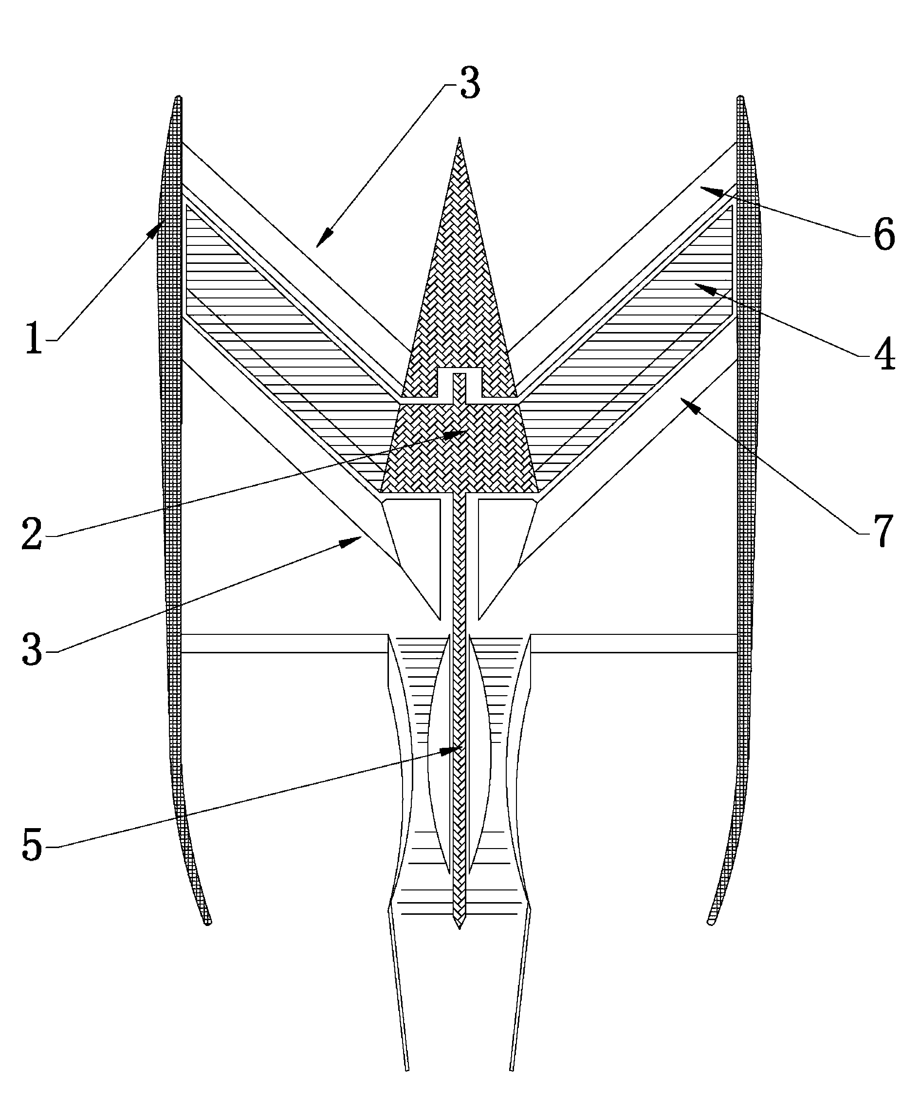
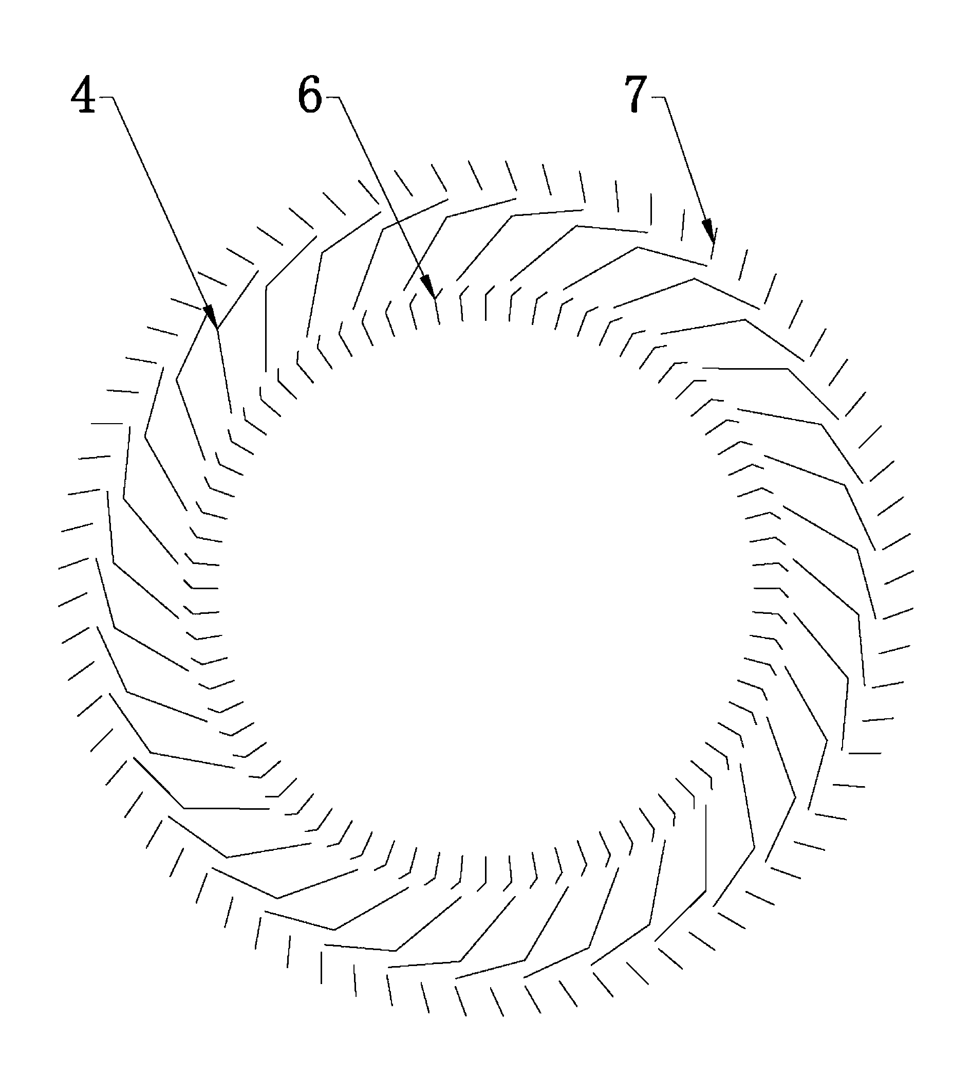
[0020] Such as Figure 1-2 Shown: a fan mechanism for a turbofan engine, including stator blades 3 fixed on the inner wall of the engine casing 1, rotor blades 4 fixedly connected to the blisk 2, the blisk 2 is connected to one end of the rotating shaft 5, wherein The stator blades 3 and the rotor blades 4 are distributed on the circumferential surface of the blisk 2 in a funnel shape as a whole, and the distribution density of the stator blades 3 is greater than that of the rotor blades 4. In the case of a change, the area of ​​the blade air intake is greatly increased, that is, the working area of ​​the stator blade 3 and the rotor blade 4 is increased. The stator vane 3 includes a stator guide vane 6 and a stator reverse thrust vane 7, the stator guide vane 6 and the stator reverse thrust vane 7 are respectively arranged on the outer side and the in...


PUM


Abstract

The invention discloses a fan mechanism of a turbo-fan engine. The fan mechanism comprises stator vanes (3) and rotor vanes (4), wherein the stator vanes (3) and the rotor vanes (4) are distributed on the circumferential surface of a vane disc (2) in an overall funnel-shaped manner, the stator vanes (3) include stator guide vanes (6) and stator reverse thrust vanes (7), the stator vanes (6) and the stator reverse thrust vanes (7) are arranged outside and inside the rotor vanes (4). By the setting mode of the stator vanes and the rotor vanes, working areas of the stator vanes and the rotor vanes are increased, the efficiency of air entering the rotor vanes is improved and the air pressure is increased. Compared with the like engine, aircraft engines with turbo-fan mechanisms have the advantages of fuel economization, great promotion force, quick acceleration, and the acceleration, fuel saving volume and fan pressure ratio are all increased by 50% or above. The fan mechanism is stable in performance and long in service life and suitable for promotion use.

Description

technical field [0001] The invention relates to the technical field of engines, in particular to a fan mechanism for a turbofan engine which can improve the efficiency and performance of the engine. Background technique [0002] The fan of the existing engine, due to the resistance of the fan as the air when the engine fan takes in air at high speed, the fan limits the speed and air intake volume of the air intake, making it difficult for the engine fan to increase the air intake volume and exhaust volume; In the high-speed rotation, the reverse thrust of the larger exhaust also reduces the working efficiency of the fan, that is, reduces the working efficiency of the engine. Contents of the invention [0003] The purpose of the present invention is to provide a fan mechanism for a turbofan engine that can improve the efficiency and performance of the engine, aiming at the defects in the prior art. [0004] The purpose of the present invention is solved by the following te...

Claims


Application Information

Patent Timeline
Patent Type & Authority Applications(China)
IPC IPC(8): F04D29/28F04D29/30
Inventor 薛文义薛振威薛圣威
Owner 薛文义
Learn More