System for delivering air from a multi-stage compressor to a turbine portion of a gas turbine engine

a gas turbine engine and compressor technology, applied in the field of gas turbine engines, can solve the problems of inefficiency of high pressure extraction air, inefficient combining high and low pressure air, and insufficient pressure of medium and low pressure turbine inputs, so as to reduce fuel burn rate, increase generator output, and reduce the effect of fuel burn ra

Active Publication Date: 2011-11-15
GENERAL ELECTRIC CO
View PDF10 Cites 21 Cited by
  • Summary
  • Abstract
  • Description
  • Claims
  • Application Information

AI Technical Summary

Benefits of technology

[0005]In accordance with one aspect of the invention, a system for bleeding air from a multi-stage compressor to provide bypass air to a turbine to optimize turbine performance during low turn down and / or operation below design temperature is provided. The system includes a turbine having a plurality of extraction air input ports including a high pressure input port, a medium pressure input port and a low pressure input port. In addition to the turbine, the system includes a multi-stage compressor having a plurality of extraction air outputs including at least one high pressure extraction air output, at least one medium pressure extraction air output and at least one low pressure extraction air output. A valve is fluidly connected to the at least one high pressure extraction air output, at least one low pressure extraction air output and low pressure input port of the turbine. The valve is selectively operated to fluidly connect the at least one low pressure extraction air output with the low pressure input port during normal operating conditions and fluidly connect the high pressure extraction air output and the low pressure input port during one of a low turn down condition and operation below design temperatures.
[0008]Surprisingly however, it has been found that routing the high pressure extraction to the low pressure turbine input will cause higher than design pressure ratios on the low pressure input. The increase in air to the low pressure input results in less air being passed to a combustor in the turbine engine. With less air being passed to the combustor, less fuel is required to maintain combustor firing temperature within emissions compliance. Using less fuel also lowers fuel burn rate and, as a consequence, plant output can be lowered to a level beyond what is currently possible, that is, the present invention enables engine turndown to 15%-20% of full output. In this manner, a power plant can operate at a very low turndown and remain on the grid during a period of low demand while at the same time operating generators in a cost efficient manner. As a result, the power plant can quickly ramp up to provide additional output if another system goes down. In addition, by remaining on the grid, the generator is first in line to provide power when demand increases and generator output can be increased to baseload levels.

Problems solved by technology

During non-optimal operating conditions, high pressure bypass extraction air is delivered from the high pressure compressor extraction to both the high pressure input port and the low pressure input port on the turbine.
However, the medium and low pressure extractions no longer have enough pressure to adequately supply the respective medium and low pressure turbine inputs.
In the past, using high pressure extraction air was considered very inefficient.
Combining high and low pressure air was deemed very inefficient and thus not cost effective.
Surprisingly however, it has been found that routing the high pressure extraction to the low pressure turbine input will cause higher than design pressure ratios on the low pressure input.

Method used


Image

  • System for delivering air from a multi-stage compressor to a turbine portion of a gas turbine engine
  • System for delivering air from a multi-stage compressor to a turbine portion of a gas turbine engine

Examples


Embodiment Construction

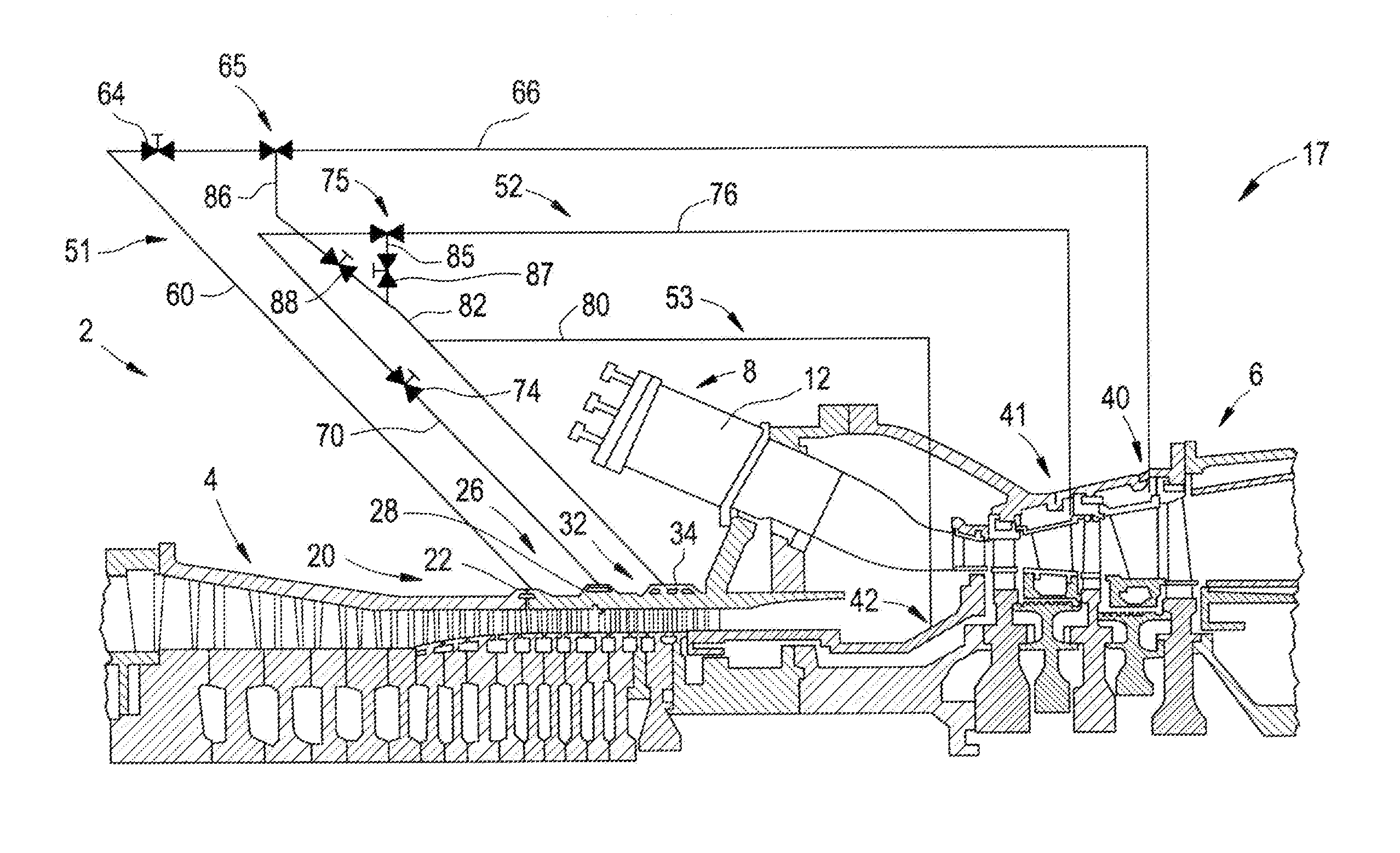
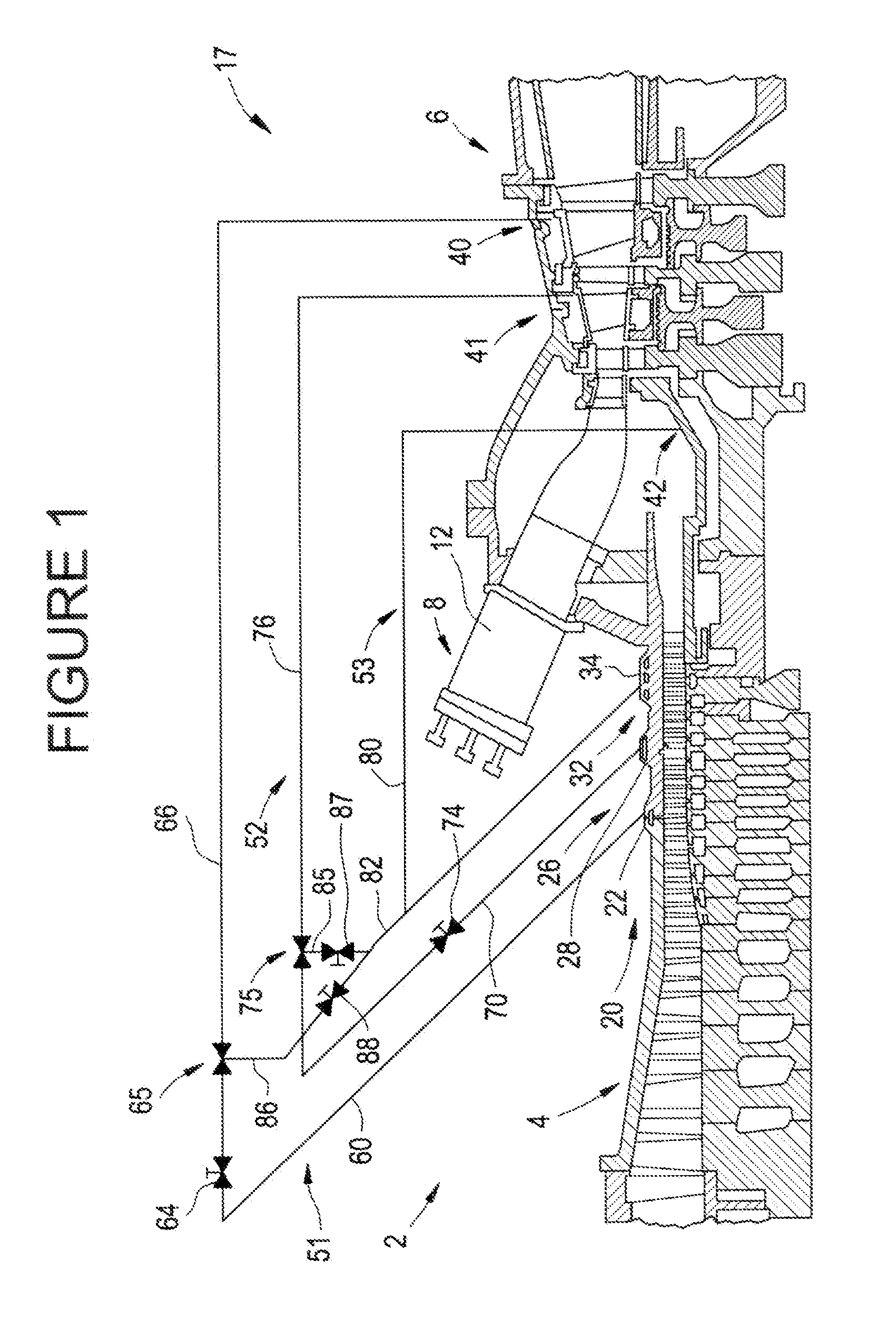
[0011]With initial reference to FIG. 1, a gas turbine engine constructed in accordance with an exemplary embodiment of the present invention is generally indicated at 2. Engine 2 includes a compressor 4 operatively connected to a turbine 6 via a shaft (not separately labeled). Engine 2 is further shown to include a combustor assembly 8 including a combustion chamber 12. Combustion gases are produced in combustor assembly 8 and used to drive turbine 6 as will be discussed more fully below.

[0012]In operation, air flows into compressor 4 and is compressed into a high pressure gas. The high pressure gas is supplied to combustor assembly 8 and mixed with fuel, for example process gas and / or synthetic gas (syngas). The fuel / air or combustible mixture is passed into combustion chamber 12 and is ignited to form a high pressure, high temperature combustion gas stream of approximately 871° Celsius (C.) to 1621° C. (1600° Fahrenheit (F.) to 2950° F.). Alternatively, combustor assembly 8 can co...


PUM


Abstract

A system for providing air from a multi-stage to a turbine includes a turbine having a high pressure input port and a low pressure input port. The system also includes a compressor having at least one high pressure extraction air output and at least one low pressure extraction air output. A valve is fluidly connected to the at least one high pressure extraction air output, at least one low pressure extraction air output and low pressure input port of the turbine. The valve is selectively operated to fluidly connect the at least one low pressure extraction air output with the low pressure input port during normal operating conditions and fluidly connect the at least one high pressure extraction air output and the low pressure input port during a turn down condition or below design temperature operation to enhance turbine engine performance.

Description

BACKGROUND OF THE INVENTION[0001]The present invention pertains to the art of gas turbine engines and, more particularly, to a system for delivering air from a multi-stage compressor to a turbine portion of a gas turbine engine to enhance turbine engine performance during low turn down and / or operation below design temperatures.[0002]Turbine engines are designed to operate at full speed, International Organization for Standardization (ISO) conditions. That is, turbine engines are designed to utilize a defined range of input conditions, e.g., design point temperature, barometric pressure, fuel type etc, to operate within a defined speed band to produce an optimal, high, output below which operation is less than efficient. Often times however, input conditions are outside the design points, and / or a lower than full output is desired. During ISO operation, air is fed into a combustor to mix with fuel to form a high pressure, high temperature combustion product that is delivered to the ...

Claims


Application Information

Patent Timeline
Patent Type & Authority Patents(United States)
IPC IPC(8): F01D19/00F01D25/12F01D9/06F01D5/18
CPCF02C6/08F01D25/12
Inventor ROUSH, ERIC DAVIDPARKER, WILLIAM ANDREW
Owner GENERAL ELECTRIC CO
Why Eureka
Try Eureka