Skewed rotor core and manufacturing method thereof and motor comprising skewed rotor core

A technology of a skewed rotor and a manufacturing method, which is applied in the manufacture of stator/rotor body, magnetic circuit rotating parts, magnetic circuit shape/pattern/structure, etc., can solve the problem of reducing motor vibration and noise, high processing cost, and difficult to eliminate high Sub-harmonics and other problems, to achieve the effect of reducing processing cycle and cost, eliminating high-order harmonics, reducing vibration and noise

Active Publication Date: 2013-04-24
XIANGTAN ELECTRIC MFG CORP LTD
View PDF6 Cites 10 Cited by
  • Summary
  • Abstract
  • Description
  • Claims
  • Application Information

AI Technical Summary

Problems solved by technology

[0009] The disadvantages of this existing conventional one-way skewed rotor core are as follows: on the one hand, the iron core slots and keyways of the rotor punching sheet of the one-way skewed rotor core are punched before lamination, and in order to Make sure that the iron core groove of the one-way skewed rotor core formed by laminating the rotor punching sheets is oblique in the axial direction, and the key groove is straight in the axial direction, then each rotor punching sheet needs to be punched twice. In addition, the skewed rotor core has high requirements on the skewed slot, so the punching equipment of the rotor punching is required to have high precision to ensure that the indexing of the skewed rotor core's skewed groove meets the requirements, resulting in the rotor punching Long processing cycle and high processing cost
On the other hand, the conventional one-way skewed rotor core is difficult to eliminate high-order harmonics and reduce the vibration and noise of the motor

Method used


Image

  • Skewed rotor core and manufacturing method thereof and motor comprising skewed rotor core
  • Skewed rotor core and manufacturing method thereof and motor comprising skewed rotor core
  • Skewed rotor core and manufacturing method thereof and motor comprising skewed rotor core

Examples


Embodiment Construction

[0029] The present invention will be further described below in conjunction with accompanying drawing:

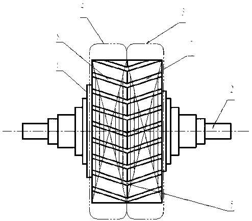
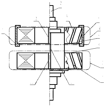
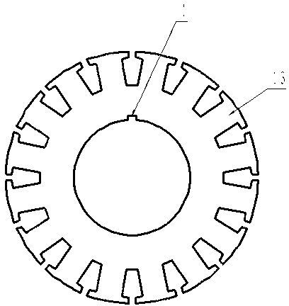
[0030] refer to Figure 1 to Figure 3 , a skewed rotor core, which includes a rotating shaft 2, a skewed rotor core I3 and a skewed rotor core II4, the skewed rotor core I3 and the skewed rotor core II4 are laminated by rotor punching sheets The oblique direction of the oblique rotor core I 3 core slot I 7 and the oblique rotor core II 4 iron core slot II 8 are symmetrically arranged, and the oblique rotor core I 3 and oblique rotor iron The inclined grooves of the core slots of core II 4 form inflection points 5 at the junction. In order to stack and guide, the inner hole of each rotor punch I13 of the skewed rotor core I3 is provided with a guide keyway I1, and the inner hole of each rotor punch II of the skewed rotor core II4 is also provided with a guide keyway II; After the rotor core I3 is stacked, the connection keyway I11 is integrally processed, and the skewed ro...


PUM


Abstract

The invention relates to a skewed rotor core which comprises a rotating shaft and a skewed rotor core, wherein the skewed core consists of two or more than two one-way skewed cores; the two adjacent one-way skewed cores have different inclined directions; an inflection point is formed at the intersection of adjacent two skewed slots; and the one-way skewed cores is formed by laminating rotor sheets. By adoption of a connecting key groove through which the one-way skewed rotor core in each skewed section is laminated and correspondingly the one-way skewed rotor core in a skewed section is generally processed, each rotor sheet can be directly punched on a common punch press, so that the processing period and cost are greatly reduced. The invention relates to a motor comprising the skewed rotor core, and a method for manufacturing the skewed rotor core.

Description

technical field [0001] The invention relates to the field of motors, in particular to a skewed rotor iron core, a manufacturing method thereof and a motor including the iron core. Background technique [0002] The conventional chute rotor core is a unidirectional chute rotor core, including the shaft and the chute rotor core. Laminated on the iron core shaft sleeve, the two become one and then set on the rotating shaft together. After manufacturing and forming, the iron core slot of the one-way inclined rotor iron core is an inclined slot in the axial direction, and the inclined slot of the iron core slot There is only one direction, that is, the axis of the iron core slot of the one-way skewed rotor core and the axis of the rotor core form an included angle in only one direction. This kind of unidirectional inclined slot rotor core, because the inclined slots all face one direction, although the higher harmonics of the motor with the conventional straight slot iron core ar...

Claims


Application Information

Patent Timeline
Patent Type & Authority Applications(China)
IPC IPC(8): H02K1/22H02K15/02
Inventor 王菁雷雄郑毅锋陈震林孙良友
Owner XIANGTAN ELECTRIC MFG CORP LTD
Why Eureka
Try Eureka