a switching circuit

A switching circuit and switching tube technology, applied in the field of semiconductor applications, can solve the problems of high hardware cost, high circuit complexity and high space requirements, reduce hardware cost and development cost, avoid code writing work, and have high anti-interference performance. Effect

Active Publication Date: 2016-01-20
GOERTEK INC
View PDF5 Cites 1 Cited by
  • Summary
  • Abstract
  • Description
  • Claims
  • Application Information

AI Technical Summary

Problems solved by technology

[0004] However, existing switching circuits have many shortcomings, for example,
[0005] For the first solution, mechanical limit switches are generally relatively large in size, difficult to implement in structure, relatively complicated in operation, and there is an Electro-Magnetic Interference (EMI) problem at the moment of connection and disconnection, and the service life is relatively long. Shorter, its structural design has higher space requirements, which affects the flexibility of the overall switch circuit structural design;
[0006] Compared with the first solution, the second solution can reduce the space occupied by the switch circuit, but the switch circuit of the second solution needs a special control chip or MCU, the required hardware cost is relatively high, the circuit complexity is large, and the Work that requires additional coding
Moreover, because the input of the trigger button or the IQ of the MCU itself is very sensitive to voltage, the probability of electrostatic induction is relatively high, and it is difficult to achieve electrostatic discharge (Electro-Static discharge, ESD), which makes the product face electromagnetic compatibility (ElectroMagneticCompatibility, EMC) poor problem

Method used


Image

  • a switching circuit
  • a switching circuit
  • a switching circuit

Examples


Embodiment Construction

[0032] The technical solutions of the present invention will be clearly and completely described below in conjunction with the accompanying drawings of the present invention. Apparently, the described embodiments are only some of the embodiments of the present invention, not all of them. Based on the embodiments of the present invention, all other embodiments obtained by persons of ordinary skill in the art without creative efforts fall within the protection scope of the present invention.

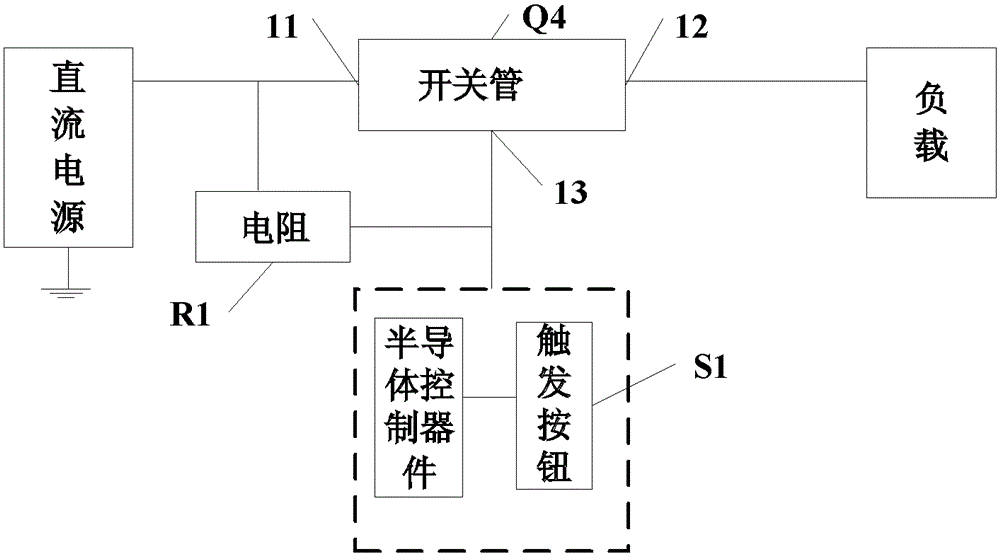
[0033] Embodiment 1 of the present invention provides a switch circuit, see figure 1 , the switch circuit includes a trigger button S1, a semiconductor control device and a switch tube Q4, the switch tube includes an input terminal 11, an output terminal 12 and a control terminal 13, when the voltage difference between the input terminal 11 and the control terminal 13 satisfies the requirement to open condition, the switch tube is conducted between the input terminal 11 and the output term...


PUM


Abstract

The invention discloses a switching circuit which is capable of reducing space requirement of products, and enhancing flexibility of product design and prolonging service lives of the products. Besides, the switching circuit is high in anti-disturbance performance and is reliable in performance. The switching circuit comprises a trigger button, a semiconductor control component and a switch tube. When the switching circuit is in an off-state and the trigger button is triggered, the switch tube is conducted, and the switching circuit is switched from the off-state to an on-state. Besides, the semiconductor control component is conducted, and the conducted semiconductor control component keeps the on-state of the switching circuit. When the switching circuit is in the on-state and the trigger button is triggered, current flowing through the semiconductor control component is bypassed, and the semiconductor control component is turned off. After the trigger button bounces back, the switch tube is cut off, and when the switch tube is cut off, the switching circuit is switched from the on-state to the off-state.

Description

technical field [0001] The invention relates to the technical field of semiconductor applications, in particular to a switch circuit capable of realizing reliable power on and off and having a simple structure. Background technique [0002] The switch circuit is a part that must be used in most systems. It is used to turn on or off the power supply between the main power supply and the system, or to control the power supply relationship between the system power supply and the subsystem. [0003] In the existing switching circuits, there are mainly two schemes as follows: the first scheme directly uses mechanical limit switches, and through mechanical movement, the circuit is physically turned on or off; the second scheme uses complex The chip is made into a special control switch circuit to realize the conduction or disconnection between the input and output (IO), or a combination of a Microprogrammed Control Unit (MCU) and a trigger button is used to control the state of th...

Claims


Application Information

Patent Timeline
Patent Type & Authority Patents(China)
IPC IPC(8): H03K17/72
Inventor 周靖刘忠远陈立国徐小龙姜斌斌
Owner GOERTEK INC
Why Eureka
Try Eureka