Electric vacuum cleaner
A vacuum cleaner, electric technology, applied in vacuum cleaners, suction filters, chemical instruments and methods, etc., can solve the problems of large transmission loss, vibration attenuation, etc., and achieve the effect of low noise
- Summary
- Abstract
- Description
- Claims
- Application Information
AI Technical Summary
Problems solved by technology
Method used
Image
Examples
no. 1 approach
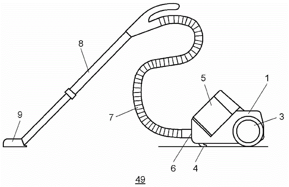
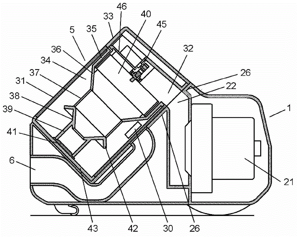
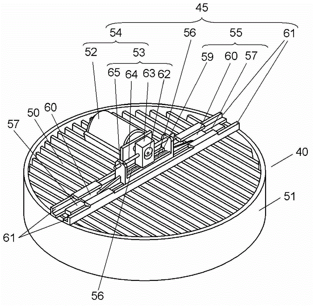
[0037] figure 1 It is a side view showing the appearance of electric vacuum cleaner 49 according to the first embodiment of the present invention. figure 2 It is a sectional view showing the main structure of the main body of the electric vacuum cleaner 49 . image 3 It is a perspective view which shows the structure of the filter 40 and the dust removal part 45 of this electric vacuum cleaner 49. As shown in FIG. Figure 4A It is a top view which shows the structure of the filter 40 and the dust removal part 45 of this electric vacuum cleaner 49. As shown in FIG. Figure 4B It is a sectional view which shows the structure of the filter 40 and the dust removal part 45 of this electric vacuum cleaner 49. As shown in FIG. Figure 4C It is a sectional view which shows the structure of the filter 40 and the dust removal part 45 of this electric vacuum cleaner 49. As shown in FIG.
[0038] Such as figure 1 As shown, wheels 3 and casters 4 are mounted on the outside of the va...
no. 2 approach
[0085] Next, the structure of the dust removal part 96 of the electric vacuum cleaner which concerns on 2nd Embodiment of this invention is demonstrated in detail using drawings. Figure 8 It is a partial sectional view showing the structure of the filter 40 and the dust removal part 96 of the electric vacuum cleaner concerning 2nd Embodiment of this invention. In addition, the same code|symbol is attached|subjected to the same part as the part demonstrated using 1st Embodiment, and the description is abbreviate|omitted. In addition, the overall structure of the electric vacuum cleaner of this embodiment is the same as figure 1 and figure 2 The illustrated electric vacuum cleaner 49 has the same structure.
[0086] Such as Figure 8 As shown, the dust removal unit 96 of the present embodiment is different from the dust removal unit 45 of the first embodiment in that a rubber member arranged in a gap in the groove portion 59 is used as the elastic body of the elastic porti...
no. 3 approach
[0091] Next, the structure of the dust removal part 97 of the electric vacuum cleaner which concerns on 3rd Embodiment of this invention is demonstrated in detail using drawings. Figure 9 It is a sectional view showing the structure of the filter 40 and the dust removal part 97 of the electric vacuum cleaner concerning 3rd Embodiment of this invention, Figure 10 It is a perspective view which shows the structure of the dust removal tool 85 of this electric vacuum cleaner. In addition, the same code|symbol is attached|subjected to the same part as the part demonstrated using 1st Embodiment, and description is abbreviate|omitted. In addition, the overall structure of the electric vacuum cleaner of this embodiment is the same as figure 1 and figure 2 The illustrated electric vacuum cleaner 49 has the same structure.
[0092] Such as Figure 9 and Figure 10 As shown, the difference between the structure of the dust removal part 97 of this embodiment and the dust removal ...
PUM
 Abstract
Description
Claims
Application Information
 - R&D Engineer
- R&D Manager
- IP Professional
- Industry Leading Data Capabilities
- Powerful AI technology
- Patent DNA Extraction
Browse by: Latest US Patents, China's latest patents, Technical Efficacy Thesaurus, Application Domain, Technology Topic, Popular Technical Reports.
© 2024 PatSnap. All rights reserved.Legal|Privacy policy|Modern Slavery Act Transparency Statement|Sitemap|About US| Contact US: help@patsnap.com


