Secondary water injection for diffusion combustion systems

A combustion system and auxiliary water pipe technology, applied in the direction of combustion chamber, turbine/propellant fuel delivery system, combustion equipment, etc., can solve the problems of large emission and unacceptable dynamic performance

Inactive Publication Date: 2013-04-24
SIEMENS ENERGY INC
View PDF12 Cites 1 Cited by
  • Summary
  • Abstract
  • Description
  • Claims
  • Application Information

AI Technical Summary

Problems solved by technology

For dispensing and mixing H 2 O's void method results in a larger NO X emissions and unacceptable dynamic performance

Method used


Image

  • Secondary water injection for diffusion combustion systems
  • Secondary water injection for diffusion combustion systems

Examples


Embodiment Construction

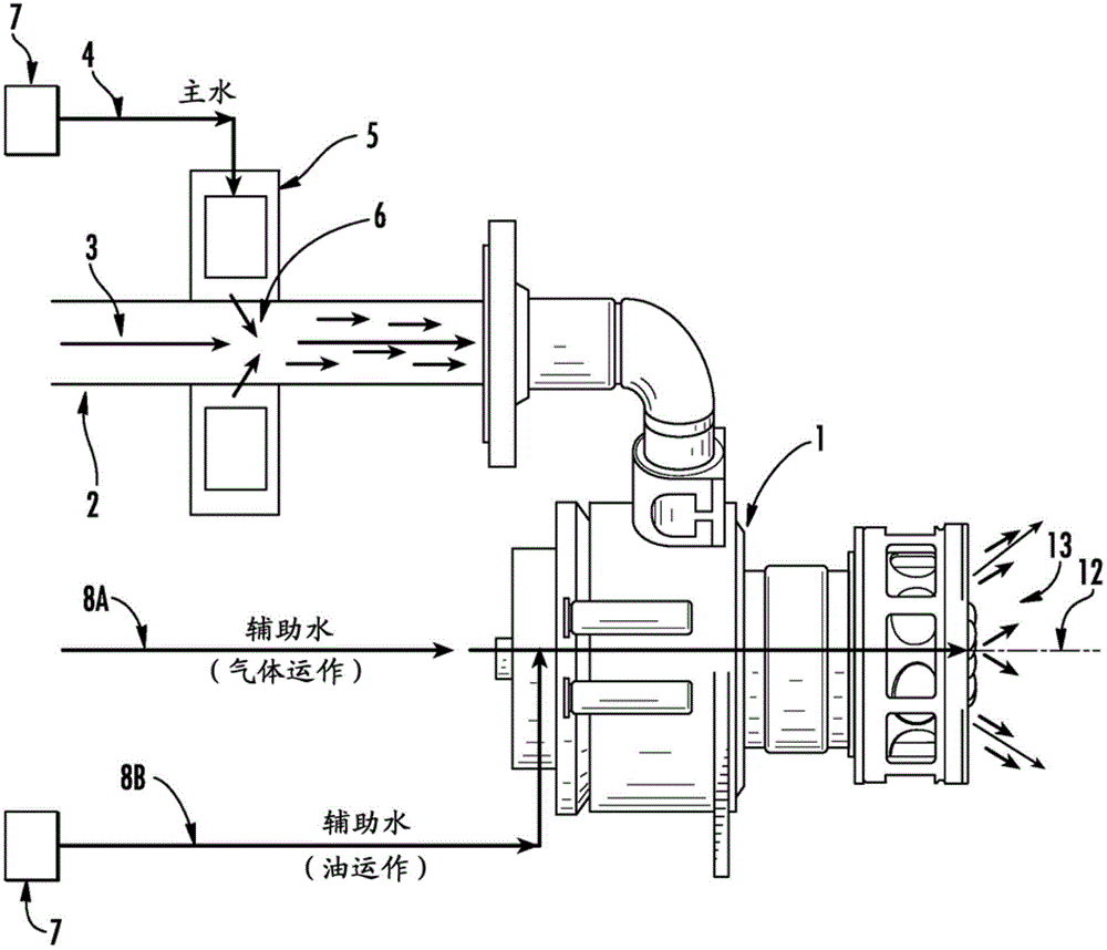
[0014] refer to figure 1 , a fuel nozzle assembly 1 for a turbine engine diffusion flame combustor is provided. Fuel line 2 may supply fuel 3 to fuel nozzle assembly 1 . A primary fluid (water) line 4 may supply a first fluid, such as water, to a water injection annular donut 5 coupled to the fuel line 2 . The water injection annular baffle 5 may be mounted to surround or enclose the fuel line 2 . The water injection annular baffle 5 may facilitate the injection of one or more water streams 6 into the fuel 3 flowing through the fuel line 2 .

[0015] Additionally or alternatively, water is injected into the combustion flame zone of the combustor located downstream of the fuel nozzle assembly 1 . Injecting water into both the fuel and the combustion zone can control exhaust emissions, especially NO X .

[0016] As used herein, water refers to its various phases, including liquid or water vapor, and combinations of liquid and water vapor, and includes liquid droplets. Here...


PUM


Abstract

Emissions and combustion dynamics of a turbine engine are managed through a combustor system that injects water into the primary fuel flow and supplies a secondary water steam to the flame zone of the combustor through a central, secondary liquid nozzle or of the fuel nozzle assembly.

Description

[0001] Cross References to Related Applications [0002] This application claims priority to US Provisional Application No. 61 / 357,616, filed June 23, 2010, the entire contents of which are hereby incorporated. technical field [0003] The present invention relates generally to diffusion flame combustors for turbine engines, and more particularly to feeding water in the form of liquid water to such diffusion flame combustors. Background technique [0004] NO X is for mononitrogen oxides NO and NO 2 (nitric oxide and nitrogen dioxide) collectively. The development of the burner focuses on meeting the tail gas NO X emissions without negatively impacting other critical areas as part of the overall system design. With diffusion flame burners, water or steam can be injected into the burner to control NO X emissions. The injected water can cause unwanted stability problems in the form of high combustion chamber dynamics and durability problems related to liner cracking. The...

Claims


Application Information

Patent Timeline
Patent Type & Authority Applications(China)
IPC IPC(8): F23R3/28F23L7/00F02C3/20F02C3/30F23R3/00F02C7/22
CPCF02C7/22F23L7/002F02C3/30F02C3/20F23R3/28F23L7/00
Inventor K.F.阿布-贾欧德S.E.芒福德
Owner SIEMENS ENERGY INC
Why Eureka
Try Eureka