Cage type optical fuze testing device

A testing device and fuze technology, which is applied in fuzes, weapon accessories, offensive equipment, etc., can solve the problems of large restrictions on the shape of the full bomb measurement, and there is no test device for testing optical fuzes.

Active Publication Date: 2014-11-05
凯迈(洛阳)测控有限公司
View PDF2 Cites 0 Cited by
  • Summary
  • Abstract
  • Description
  • Claims
  • Application Information

AI Technical Summary

Problems solved by technology

[0002] Missiles that use laser fuzes need to test their optical fuzes. In the prior art, they are all bomb tests. Most of the optical fuze test devices equipped now are snap ring hinged structures. The test module or device cooperates to complete the test of the fuze. The full-bomb measurement is greatly restricted by the shape of the full-bomb projectile and projectile parts. At present, there is no separate optical fuze test device for testing the warehouse section where the optical fuze is located.

Method used


Image

  • Cage type optical fuze testing device
  • Cage type optical fuze testing device
  • Cage type optical fuze testing device

Examples


Embodiment Construction

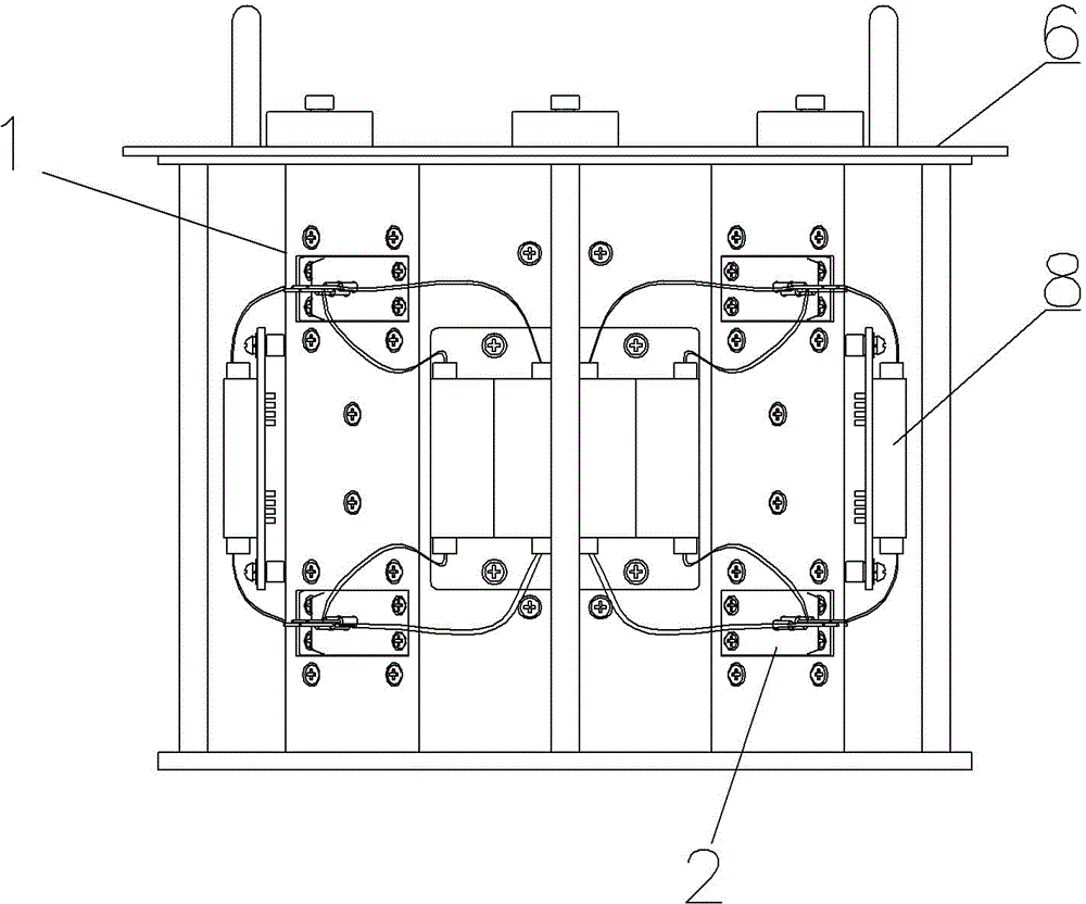
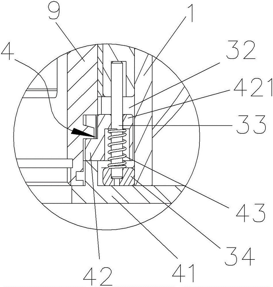
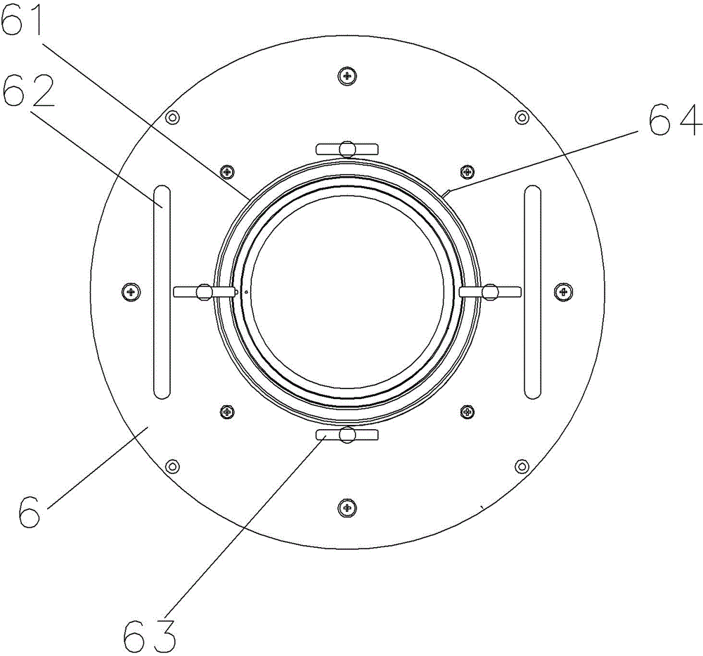
[0017] Such as Figure 1 to Figure 4 A kind of embodiment of the present invention shown, comprises cylindrical frame 1, defines the axial direction of frame 1 as the up and down direction, and the radial direction of frame 1 is horizontal direction, is provided with in the frame 1 and is provided with for being tested along the axial direction. The fuze cabin 9 is inserted into the installation channel from top to bottom, and the installation channel of the frame 1 is provided with an optical channel corresponding to the fuze cabin window 91 of the fuze cabin 9 in a one-to-one correspondence with the fuze cabin window 91 of the fuse cabin 9 and is provided with a transceiver in the optical channel. The optical collimator 2 for the optical signal, the terminal of the optical collimator 2 is exposed outside the corresponding window opened outside the frame 1 and is connected with the optical switch 8 installed on the outer surface of the frame 1 through an optical cable. The in...


PUM


Abstract

The invention discloses a cage type optical fuze testing device, which comprises a cylindrical framework, an installation channel which enables insertion of a fuse cabin to be tested from top to down and extends along an axial direction is provided in the framework, an optical channel is provided on the installation channel of the framework along the radial direction, and a light collimator is provided in the optical channel; a peripheral locating surface, a lower locating surface and a slide-stopping and positioning structure, a lock block and a installing hole for filling with the fuse cabin which is communicated with the installation channel are provided on the top of the framework, and a compaction surface which directly clamps the upper end of the fuse cabin or clamps through a baffle plate in the installing hole is provided at the lower part of the lock block. The cage type optical fuze testing device has the effects of clamping the fuse cabin, conducting an optical path, and receiving and sending the fuse signals.

Description

technical field [0001] The invention relates to a testing device for an optical fuze. Background technique [0002] Missiles that use laser fuzes need to test their optical fuzes. In the prior art, they are all bomb tests. Most of the optical fuze test devices equipped now are snap ring hinged structures. The test modules or devices cooperate to complete the test of the fuze. The full-bomb measurement is greatly restricted by the shape of the full-bomb projectile and projectile parts. At present, there is no separate optical fuze test device for testing the compartment where the optical fuze is located. Contents of the invention [0003] The object of the present invention is to provide an optical fuze testing device capable of locating the compartment where the optical fuze is located and its fuze window so as to facilitate the testing work. [0004] The technical solution of the present invention is: a cage-type optical fuze testing device, which includes a cylindrical ...

Claims


Application Information

Patent Timeline
Patent Type & Authority Patents(China)
IPC IPC(8): F42C21/00
Inventor 徐卿
Owner 凯迈(洛阳)测控有限公司
Why Eureka
Try Eureka