Stator stamping and motor

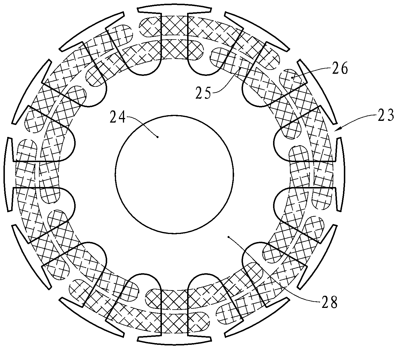
A stator punching and stator core technology, applied in the direction of magnetic circuit shape/style/structure, magnetic circuit static parts, winding conductor shape/style/structure, etc., can solve the unfavorable inner coil 25 and outer coil 26 winding Manufacturing, insulation treatment process is complicated, coil winding is difficult, etc., to achieve the effect of reducing winding difficulty, reducing production cost, and reducing insulation requirements

Inactive Publication Date: 2013-05-01
GREE ELECTRIC APPLIANCES INC +4
View PDF5 Cites 8 Cited by
  • Summary
  • Abstract
  • Description
  • Claims
  • Application Information

AI Technical Summary

Problems solved by technology

Since two adjacent inner coils 25 will be wound in the same slot 23, and two adjacent outer coils 26 will also be wound in the same slot 23, resulting in two adjacent inner coils 25 or adjacent The distance between the two outer coils 26 is too close, which brings great inconvenience to the winding of the coils and makes the winding of the coils very difficult
[0010] In addition, because the distance between the inner coil 25 and the outer coil 26 is also very short, this puts forward very high requirements for the insulation treatment between the inner coil 25 and the outer coil 26, so the insulation between the inner coil 25 and the outer coil 26 The processing process is complicated, and it is not conducive to the winding of the inner coil 25 and the outer coil 26, resulting in high production costs of the motor

Method used


Image

  • Stator stamping and motor
  • Stator stamping and motor
  • Stator stamping and motor

Examples


Embodiment Construction

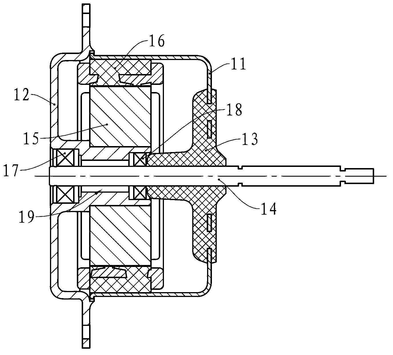
[0030] The motor of the present invention has a housing and end covers located on both sides of the housing. The housing and the end covers form a cavity, and a stator and a rotor are installed in the cavity. The motor in this embodiment is an external rotor motor, that is, the stator is located in the middle of the motor, the rotor is sleeved outside the stator, and the middle of the stator is provided with a shaft hole. The rotor shaft is installed in the middle of the rotor, and the rotor shaft can pass through the shaft hole to output power outward.

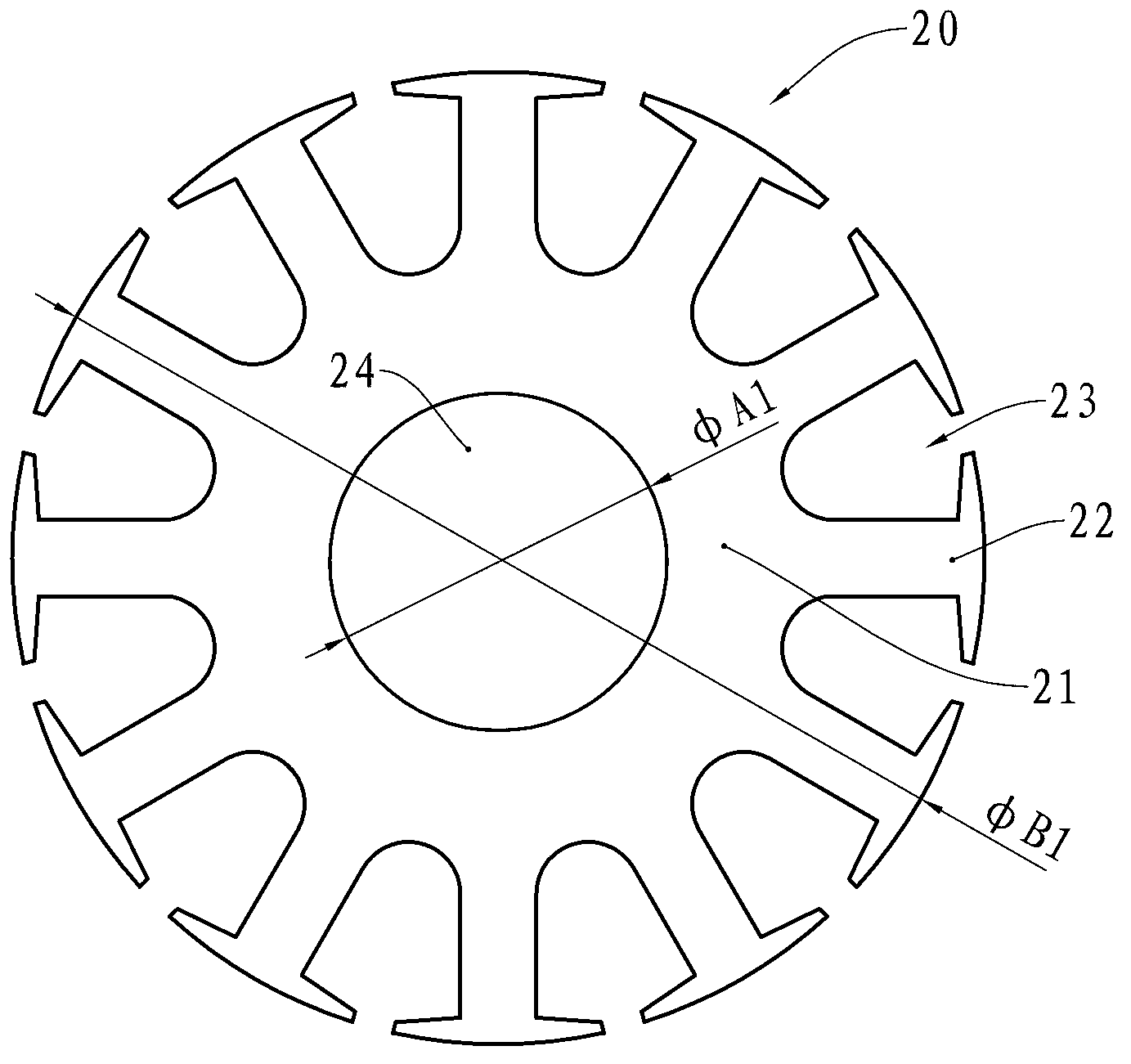
[0031] The stator has a stator core and a coil wound on the stator core, and the stator core is formed by laminating a plurality of stator punches with the same shape. see Figure 4 , the stator punching sheet 30 of the present embodiment is formed by stamping silicon steel sheets, which is roughly annular, and is provided with an annular yoke 31, the middle part of the yoke 31 is provided with an inner circular hole 35, and...


PUM


Abstract

The invention provides a stator stamping and a motor. The stator stamping is provided with an annular yoke and a plurality of teeth, the teeth are outwardly extended from the yoke along the radial direction of the stator stamping, a notch is formed between each two neighboring teeth, moreover, the middle of the stator stamping is provided with an inner round hole, wherein the notches are shallow notches and deep notches, which are arranged alternately, and the opening height of the deep notch is greater than the total height of the shallow notch. The motor is provided with a stator and a rotor, the stator is provided with a stator core made of the laminated stator stampings and coils wound on the stator core, the coils are a plurality of inner coils and a plurality of outer coils, each inner coil is wound between two deep notches, and each outer coil is wound between two shallow notches. The invention can decrease the difficulty of the coil-winding process; moreover, the coils are not overlapped spatially, so that the requirement on the insulation of the coils is decreased, and thereby the production cost of the motor is reduced; moreover, when the motor operates, the magnetic density is more uniform, and operation is more stable.

Description

technical field [0001] The invention relates to the field of motors, in particular to an outer rotor type motor and a stator stamping plate used in the motor. Background technique [0002] Motors are widely used in various electrical equipment in industrial production and life. The existing motors have a stator and a rotor. The rotor shaft is installed in the rotor and rotates with the rotation of the rotor, thereby outputting power. According to the positional relationship between the rotor and the stator, existing motors are divided into inner rotor motors and outer rotor motors. The rotor of the inner rotor motor is installed in the stator, while the outer rotor motor has the stator installed in the rotor. [0003] Usually, the inner rotor type motor has a housing and end covers located at both ends of the housing. The housing and the end covers enclose a cavity. The stator and the rotor are installed in the cavity, and the stator has a stator core and is wound on the sta...

Claims


Application Information

Patent Timeline
Patent Type & Authority Applications(China)
IPC IPC(8): H02K1/16H02K3/12
Inventor 陈川礼刘伟兵
Owner GREE ELECTRIC APPLIANCES INC
Why Eureka
Try Eureka