Method for generating cosine differential signal
A technology of signal generation and cosine difference, applied in electric pulse generator circuits, instruments, computer control, etc., can solve problems such as complex hardware circuits, low precision, and influence of output waveforms, and achieve high precision, convenient operation, and reliability high effect
- Summary
- Abstract
- Description
- Claims
- Application Information
AI Technical Summary
Problems solved by technology
Method used
Image

Examples
Embodiment Construction
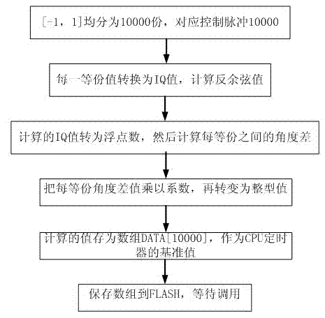
[0011] Below in conjunction with accompanying drawing, the present invention will be further described:
[0012] A cosine differential signal generation method, using a DSP digital signal processor to calculate the arccosine through C language programming; divide the domain value [-1, 1] into 10000 equal parts, that is, 10000 control pulses can be output in one cycle, Each equalization is converted into an IQ value, and the arccosine value is calculated according to the divided equalization value. The arccosine actually corresponds to the angle; the calculated IQ value is converted into a floating point number, and then the angle difference corresponding to each equalization is calculated, and each The equal angle difference is multiplied by a coefficient, and then converted into an integer value. The calculated value is stored as an array DATA[10000], and the array value is used as the basis for CPU timer calculation. In the program, the array value is stored in FLASH, waiting...
PUM
 Abstract
Description
Claims
Application Information