Matching circuit for antenna of Bluetooth headset

A matching circuit and Bluetooth headset technology, which is applied to transducer circuits, electrical components, sensors, etc., can solve the problem that the Bluetooth antenna cannot meet the bandwidth requirements, and achieve the effect of improving the overall performance

Inactive Publication Date: 2013-05-01
QINGDAO GOERTEK
View PDF4 Cites 5 Cited by
  • Summary
  • Abstract
  • Description
  • Claims
  • Application Information

AI Technical Summary

Problems solved by technology

Existing bluetooth headsets all use a matching circuit, which makes the bluetooth antenna with small bandwidth unable to meet the 80MHz bandwidth requirement of bluetooth 2400MHz to 2480MHz

Method used


Image

  • Matching circuit for antenna of Bluetooth headset
  • Matching circuit for antenna of Bluetooth headset
  • Matching circuit for antenna of Bluetooth headset

Examples


Embodiment 1

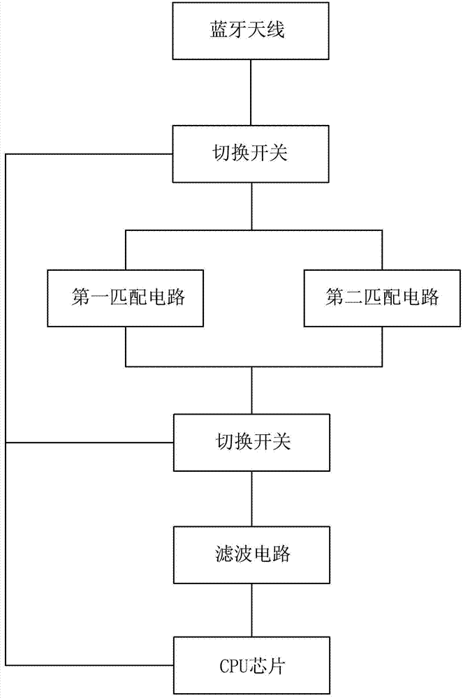
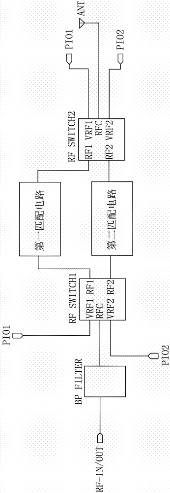
[0020] Such as figure 1 Shown, a kind of matching circuit of bluetooth earphone antenna, comprises the frequency band matching circuit that is arranged between the CPU chip of bluetooth earphone and bluetooth antenna, and frequency band matching circuit comprises two parallels acting on the frequency band matching circuit of different frequency bands, bluetooth earphone antenna The matching circuit also includes a switching switch for separately connecting each of the frequency band matching circuits according to the frequency of the Bluetooth earphone receiving or sending signals. There are two switching switches, one of which is set on the CPU chip and two parallel Between the frequency band matching circuits; another switch is set between the two parallel frequency band matching circuits and the Bluetooth antenna. The switch is also connected to the control output terminal of the CPU chip and connected to the frequency band matching circuit of the corresponding frequency ba...

Embodiment 2

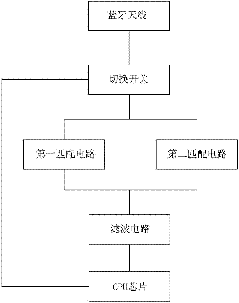
[0031] Such as image 3 As shown, the differences between this embodiment and Embodiment 1 are:

[0032] Only a switch is provided between the Bluetooth antenna and the two parallel frequency band matching circuits. This structure simplifies the circuit and also enables the original Bluetooth antenna with only a 40MHz bandwidth to work in the entire Bluetooth frequency band with a bandwidth of 80MHz.

Embodiment 3

[0034] Such as Figure 4 As shown, the differences between this embodiment and Embodiment 1 are:

[0035] Only a switch is provided between the CPU chip and two parallel frequency band matching circuits. This structure simplifies the circuit and also enables the original Bluetooth antenna with only a 40MHz bandwidth to work in the entire Bluetooth frequency band with a bandwidth of 80MHz.


PUM


Abstract

The invention discloses a matching circuit for an antenna of a Bluetooth headset and relates to the technical field of an electronic communication product. The matching circuit comprises a frequency band matching circuit arranged between a CPU(central processing unit) chip and the Bluetooth antenna of the Bluetooth headset, wherein the frequency band matching circuit comprises at least two frequency band matching circuits connected in parallel and acting on different frequency bands, the matching circuit for the antenna of the Bluetooth headset also comprises changeover switches for independently switching on the frequency band matching circuits respectively according to the signal receiving frequency or signal transmitting frequency of the Bluetooth headset, and the changeover switches are also connected with the control output end of the CPU chip and switch on the frequency band matching circuits in the corresponding frequency bands according to a signal of the control output end. The matching circuit for the antenna of the Bluetooth headset solves the technical problem that a Bluetooth antenna with small bandwidth in the prior art cannot meet the requirement on Bluetooth bandwidth. With the matching circuit, the Bluetooth antenna with small bandwidth can be applicable to the whole Bluetooth frequency band, and the overall performance of the Bluetooth headset is improved.

Description

technical field [0001] The invention relates to the technical field of electronic communication products, in particular to a matching circuit for a bluetooth earphone antenna. Background technique [0002] The Bluetooth headset is to apply Bluetooth technology to the hands-free headset, so that the user can avoid the entanglement of wires and talk easily in various ways. Since the advent of Bluetooth headsets, it has been a good tool for mobile business families to improve efficiency, and it is precisely because of this that Bluetooth headsets are becoming more and more popular. The bluetooth headset belongs to electronic products, including a headset CPU chip, a bluetooth antenna, and an antenna matching circuit arranged between the CPU chip and the bluetooth antenna. [0003] With the progress of society and the continuous improvement of people's living standards, people's requirements for Bluetooth headsets are not only satisfied in terms of functions, but also put forwa...

Claims


Application Information

Patent Timeline
Patent Type & Authority Applications(China)
IPC IPC(8): H04R3/00H04B5/00
Inventor 郭湘荣
Owner QINGDAO GOERTEK
Why Eureka
Try Eureka