
Parallel system bus construction and port configuration management method thereof

A system bus and downlink port technology, applied in transmission systems, bus networks, data exchange through path configuration, etc., can solve the problems of small bandwidth and cannot meet high bandwidth, reduce the number of pins, meet cost design requirements, Effect of Low Cost Design Requirements

Active Publication Date: 2009-03-25
HUAWEI TECH CO LTD
View PDF0 Cites 4 Cited by
  • Summary
  • Abstract
  • Description
  • Claims
  • Application Information

AI Technical Summary

Problems solved by technology

If there are four service boards, the downlink bandwidth allocated to each service board is only 200M. The bandwidth of 200M is too small to meet the high bandwidth requirements.

Method used


Image

  • Parallel system bus construction and port configuration management method thereof
  • Parallel system bus construction and port configuration management method thereof
  • Parallel system bus construction and port configuration management method thereof

Examples


Embodiment 1

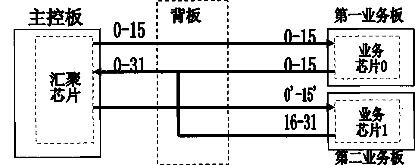
[0025] Embodiment 1: Realize the correspondence between uplink and downlink ports by adjusting the aggregation chip port of the main control board

[0026] Such as image 3 As shown, in the downstream direction, 0 to 15 downstream ports of the aggregation chip in the main control board are mapped one by one with 0 to 15 downstream ports of the service chip 0 in the first service board, and the aggregation chip in the main control board The 0' to 15' downlink ports of the second service board are mapped one by one with the 0' to 15' downlink ports of the service chip 1 in the second service board;

[0027] In the uplink direction, the 0 to 15 uplink ports of the service chip 0 in the first service board are mapped one by one with the 0 to 15 uplink ports of the aggregation chip of the main control board, and the service chip in the second service board The 16 to 31 uplink ports of the main control board are mapped one by one with the 0' to 15' uplink ports of the aggregation c...

Embodiment 2

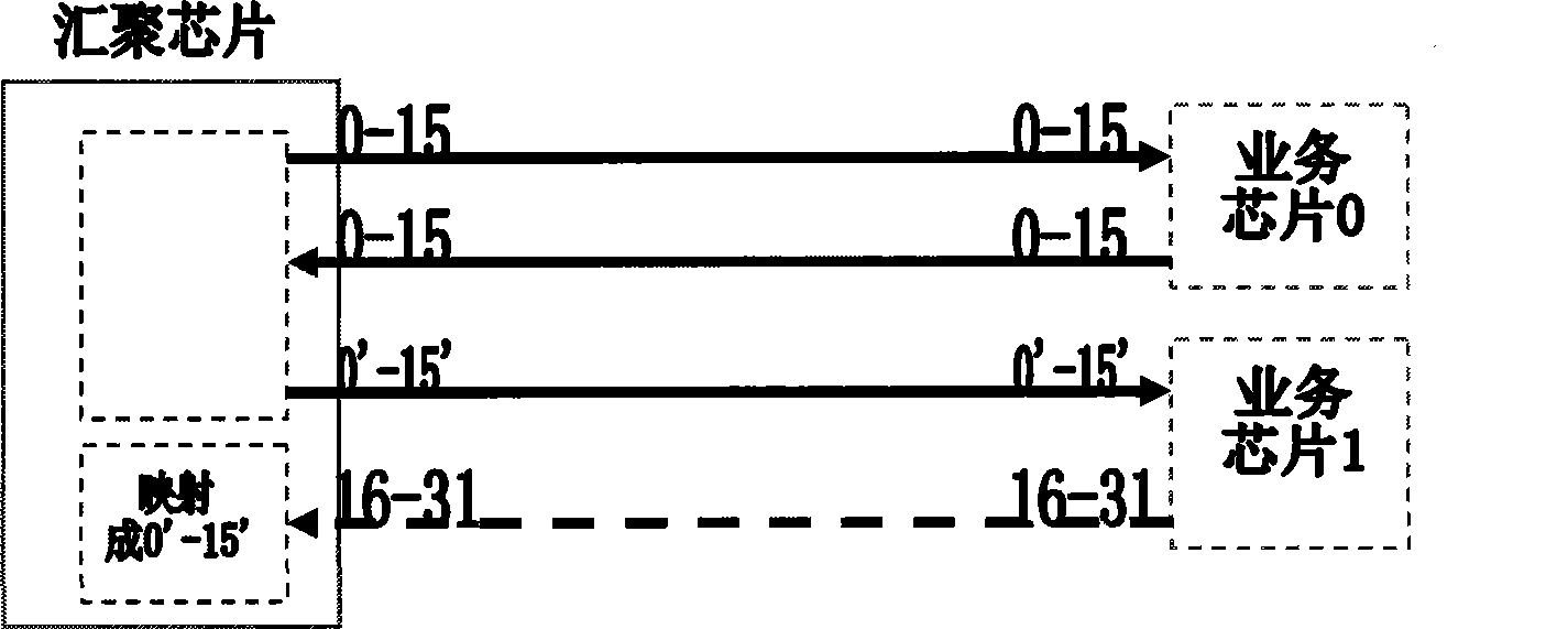
[0028] Embodiment 2: Realize the correspondence between uplink and downlink ports by adjusting the service chip ports of the service board

[0029] Such as Figure 4 As shown, in the downstream direction, 0 to 15 downstream ports of the aggregation chip in the main control board are mapped one by one with 0 to 15 downstream ports of the service chip 0 in the first service board, and the aggregation chip in the main control board The 0' to 15' downlink ports of the second service board are mapped one by one with the 16' to 31' downlink ports of the service chip 1 in the second service board;

[0030] In the uplink direction, the 0 to 15 uplink ports of the service chip 0 in the first service board are mapped one by one with the 0 to 15 uplink ports of the aggregation chip of the main control board, and the service chip in the second service board The 16 to 31 uplink ports of 1 are mapped one by one with the 16 to 31 uplink ports of the aggregation chip of the main control boar...


PUM


Abstract

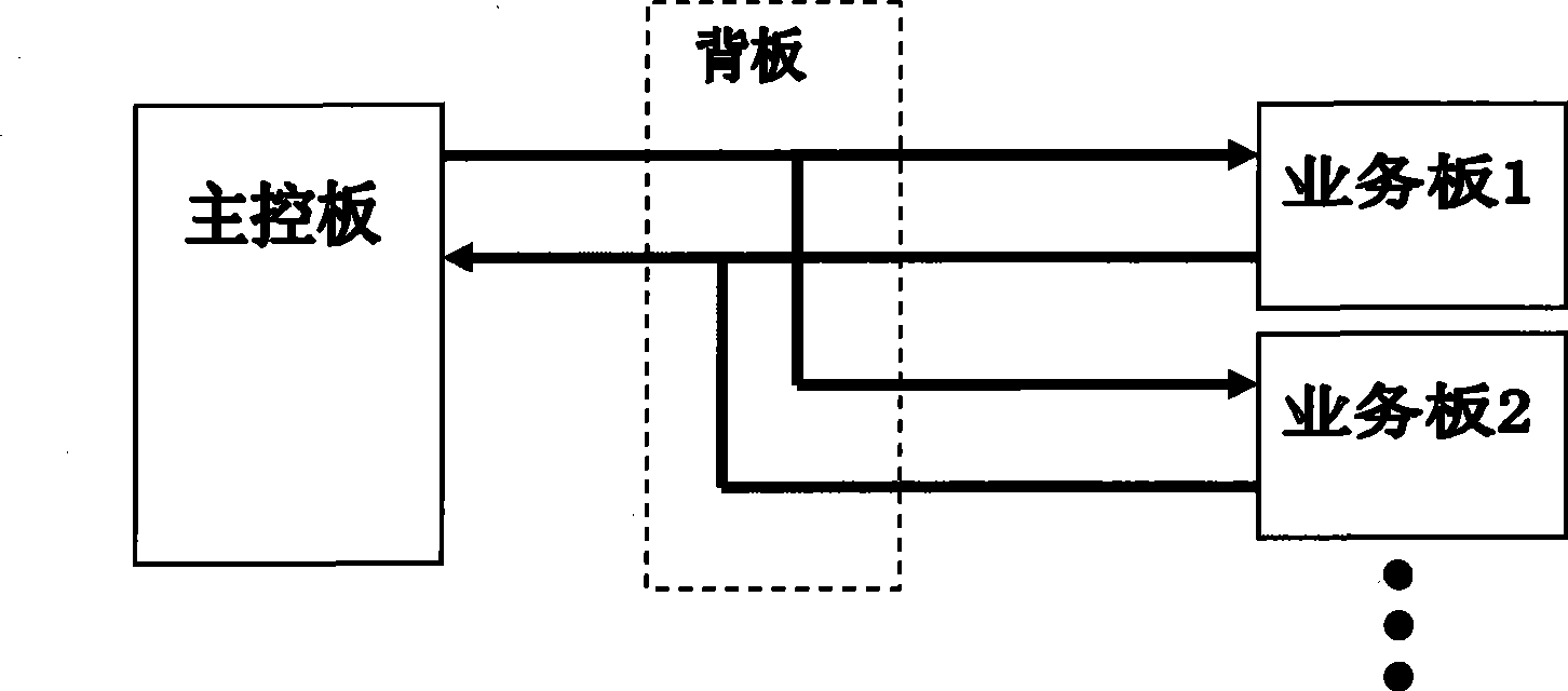
The embodiment of the invention discloses a parallel system bus architecture, which comprises a master control board and at least two service boards. In the downlink direction, the master control board and the service boards are in point-to-point connection with each other through a bus; and in the uplink direction, the master control board and the service boards are in multipoint-to-single-point connection with each other through the bus. The downlink direction refers to link from the master control board to the service boards, and the uplink direction refers to link from the service boards to the master control board. Accordingly, the embodiment of the invention also discloses a port configuration management method in the parallel system bus architecture. By implementing the parallel system bus architecture and the port configuration management method thereof, the user bandwidth requirement is satisfied by adopting uplink / downlink asymmetric bus architecture, so as to reduce the wire outgoing pressure of the master control board and the back board and reduce the number of gathered chip pins.

Description

technical field [0001] The invention relates to electronic communication technology, in particular to a parallel system bus structure and a port configuration management method thereof. Background technique [0002] With the development of communication technology, network service applications are becoming more and more mature, and users have higher and higher requirements for bandwidth. Fiber-in-copper-out has become the development trend of access networks. In optical-in copper-out, fiber-to-building ( FiberTo The Building, FTTB) network construction mode has been widely promoted. [0003] Since FTTB plug-in devices have relatively high requirements on density, cost, and volume, they usually use the backplane to directly use the parallel bus, such as UTOPIA / POS_PHY bus. This type of bus occupies too many pins of the backplane connectors of the main control board and service board, especially the main control board that supports multiple service boards requires a backplane...

Claims


Application Information

Patent Timeline
IPC IPC(8): H04L12/40H04L29/06G06F13/38
Inventor 盛晖王苏李思恩沈文良
Owner HUAWEI TECH CO LTD
Learn More