Hydraulic drive and control system for pumps using a charge pump

a technology of hydraulic drive and control system, which is applied in the direction of positive displacement liquid engine, piston pump, fluid coupling, etc., can solve the problems of electronic control system failure, system undesirable, and difficulty in quickly making corresponding changes in variable displacement hydraulic pump, so as to reduce the outlet pressure of liquid pump, reduce the pressure to the motor, and reduce the pump output pressure

Active Publication Date: 2013-01-01
BRANTLEY DANIEL R +3
View PDF13 Cites 2 Cited by
  • Summary
  • Abstract
  • Description
  • Claims
  • Application Information

AI Technical Summary

Benefits of technology

[0006]The pumping system operates the drive system and the control system almost exclusively by hydraulic fluid pressure which avoids the necessity of an electronic control system to control the pump outlet pressure which may be more complex to maintain and susceptible to failure, particularly in harsh, hostile or remote environments.
[0010]The swash plate is mechanically moved by a swash plate control which is a pressure balancing solenoid that is pressurized on one side by a low charge pressure supplied by a charge pump which charge pump is also driven by the diesel engine. The pressure balancing solenoid is pressurized on a second side by a variable control pressure which preferably is a destroking pressure that destrokes the main pump to vary its output. This control pressure is manually adjustable by a system control valve to set the maximum system pressure and maintain such pressure. This system control valve receives the high system pressure from the outlet of the main pump and has a manually rotatable valve wherein a control knob is rotated to set the max system pressure. In this regard, the control valve is adjusted which essentially generates an adjusted pressure exiting the control valve which is fed to the swash plate control solenoid as the destroke pressure to vary the swash plate in a manner that quickly varies the system pressure that is output from the main pump in correspondence to the adjusted destroke pressure supplied to the solenoid.
[0013]As the swash plate moves, it lowers the pump output pressure from the main pump which thereby reduces the pressure to the motors which in turn reduces the outlet pressure of the liquid pump. Hence, by manually adjusting the system control valve by rotating the knob, the system pressure driving the motors is raised or lowered which thereby raises or lowers the outlet pressure of the liquid pump.

Problems solved by technology

However, the system may be undesirable since fluctuations in the liquid outlet pressure may occur which may make it difficult to quickly make corresponding changes in the variable displacement hydraulic pump.
Further, the electronic control system may be subject to failure, particularly in hostile environments wherein an electronic control system may be difficult to maintain.
While some electronics may be provided primarily for system monitoring and safety shutoff, such electronics may be omitted or disabled for various reasons and the pumping system will continue to operate.

Method used


Image

  • Hydraulic drive and control system for pumps using a charge pump
  • Hydraulic drive and control system for pumps using a charge pump
  • Hydraulic drive and control system for pumps using a charge pump

Examples


Embodiment Construction

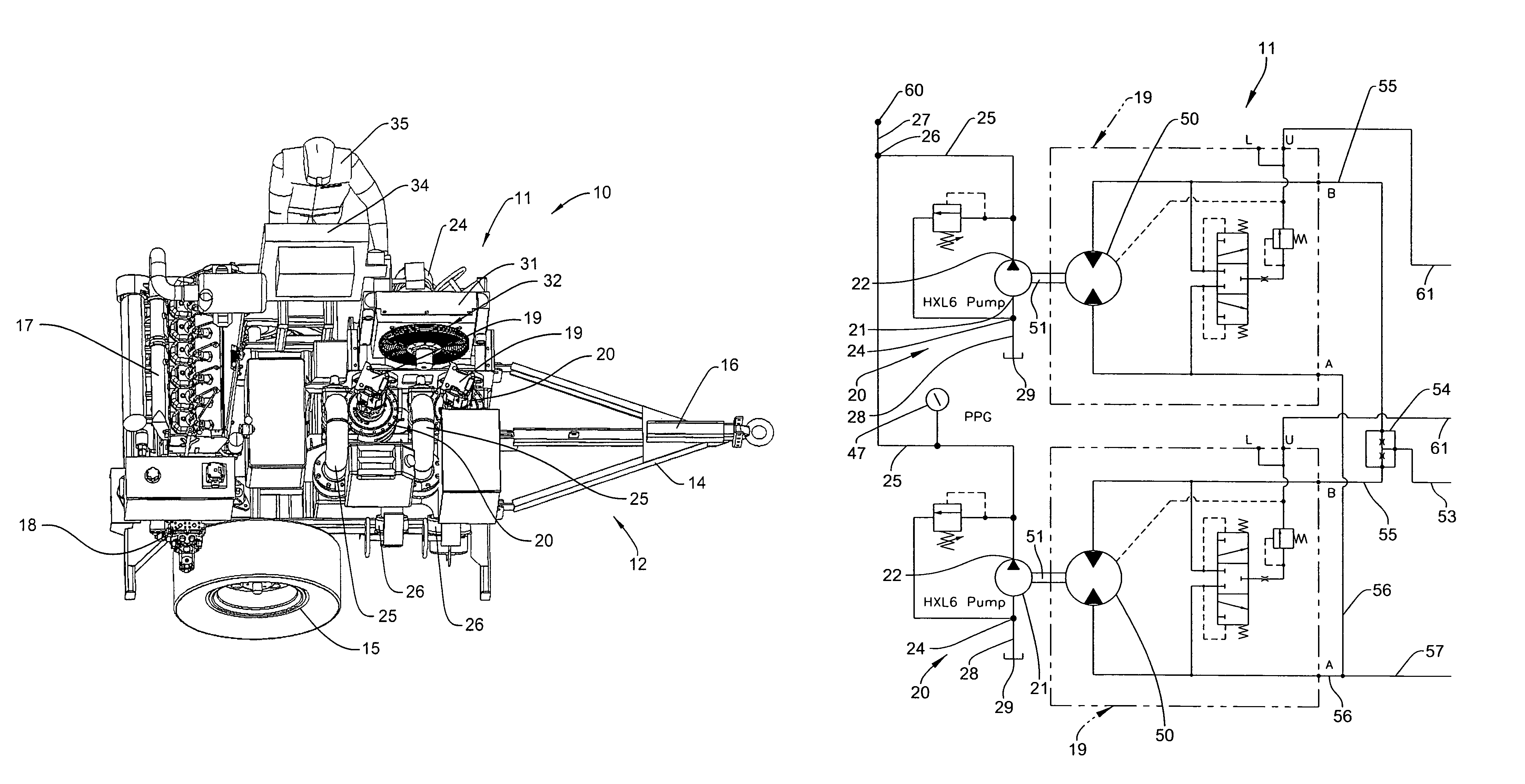
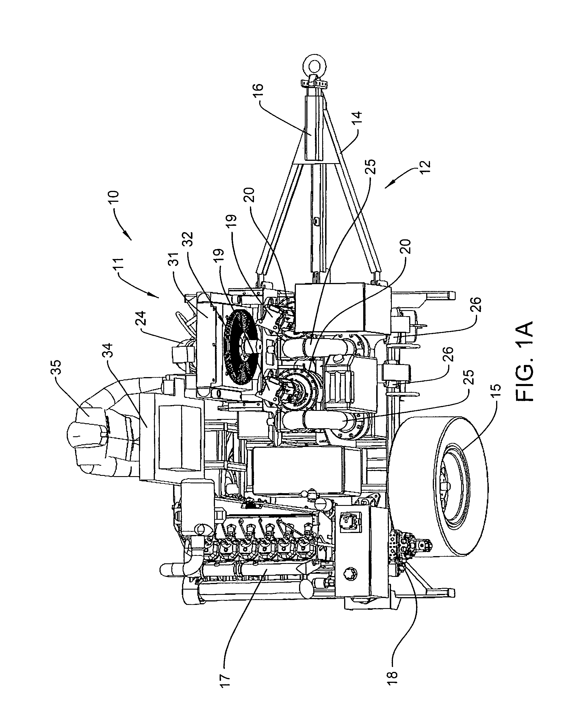
[0025]Referring to FIG. 1A, the invention relates to a fluid handling system 10 and more particularly, to a mobile pumping system 11 for use in distributing fluids, such as water, fuels or other suitable liquids. The mobile pumping system 11 is usable for various applications where it is necessary to pump fluids from remote and / or temporary storage tanks and facilities. The pumping system 11 preferably is mountable to a vehicle 12 and is a self-contained system which does not require external power sources or controls.

[0026]More particularly, the vehicle 12 preferably is a trailer comprising a trailer frame 14 having wheels 15 allowing for transport of the pumping system 11 between fluid storage sites or facilities. The pumping system 11 in particular is mounted to the trailer frame and transportable on a secondary vehicle by the hitch portion 16. It will be understood that the pumping system 11 may also have uses and applications wherein the system is mounted on a self-propelled ve...


PUM


Abstract

A pumping system is provided which is a mobile, vehicle-mounted pumping system, such as for water or fuels, which mounts on a vehicle and may be used for various applications. The pumping system operates a drive system and control system for liquid pumps almost exclusively by hydraulic fluid pressure.

Description

CROSS REFERENCE TO RELATED APPLICATION[0001]This application claims the benefit of U.S. Provisional Application Ser. No. 61 / 269,801, filed Jun. 29, 2009, which is incorporated herein by reference in its entirety.FIELD OF THE INVENTION[0002]The invention relates to a hydraulic drive and control system for a system of positive displacement pumps, and more particularly, to a system which uses a hydraulic drive system as well as a fully hydraulic control system which maintains the outlet pressure discharged from the pumps.BACKGROUND OF THE INVENTION[0003]It is known to provide pumping systems for use in mobile applications such as vehicle-mounted pumping systems. An example of one such system is disclosed in U.S. Pat. No. 6,551,073 B1 (O'Sullivan) which discloses a pumping system typically used on a fire truck. In this application, the vehicle is provided with a hydraulic drive system wherein a liquid pump for pumping water is driven by a fixed displacement hydraulic motor, which motor ...

Claims


Application Information

Patent Timeline
Patent Type & Authority Patents(United States)
IPC IPC(8): F04B9/10F04B23/04F04B17/05
CPCF04B1/324F04B17/05F04B17/06F04B23/10F04B49/002F04B49/08F04B2205/05
Inventor BRANTLEY, DANIEL R.BERGS, IVARS R.SIETSEMA, JEFFREY J.BRENNAN, MICHAEL J.
Owner BRANTLEY DANIEL R
Why Eureka
Try Eureka