Electrode and facility for chamfering the corners of a metal workpiece

A technology of metal components and components, applied in metal processing equipment, manufacturing tools, electrochemical processing equipment, etc., can solve the problems of time-consuming, unreliable testing, etc., and achieve the effect of eliminating the risk of damage

Active Publication Date: 2013-05-01
SN DETUDE & DE CONSTR DE MOTEURS DAVIATION S N E C M A
View PDF7 Cites 2 Cited by
  • Summary
  • Abstract
  • Description
  • Claims
  • Application Information

AI Technical Summary

Problems solved by technology

Not only is this test time consuming, it has also been found to be not very reliable as it depends on the orientation of the lighting and the position of the hardened imprint relative to the magnifying glass and on the quality of the imprint formed

Method used


Image

  • Electrode and facility for chamfering the corners of a metal workpiece
  • Electrode and facility for chamfering the corners of a metal workpiece
  • Electrode and facility for chamfering the corners of a metal workpiece

Examples


Embodiment Construction

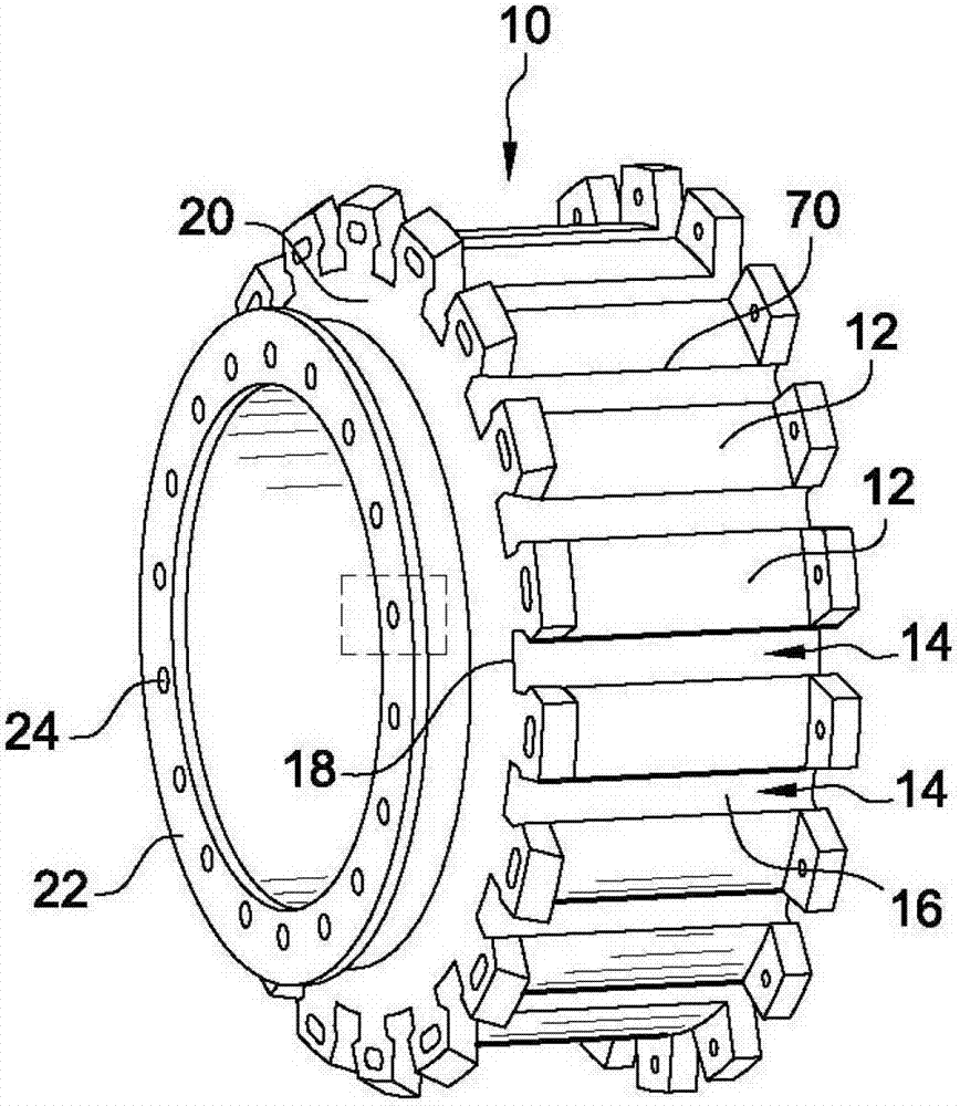
[0033] Initially referring to a rotor disk 10 in a turbomachine is shown figure 1 , the rotor disk 10 has on its periphery a plurality of key bars 12 interspersed with slots 14 for receiving wedge-shaped blade roots.

[0034] Thus, the bottom surface 16 of each groove 14 forms a right-angled edge 18 with the upstream face 20 and the downstream face of the disc 10 . Burrs are formed on these right angled sides when grooves 14 are formed in disc 10 and these sides 18 or corners need to be machined to remove the burrs and avoid any injury to the operator while handling disc 10 .

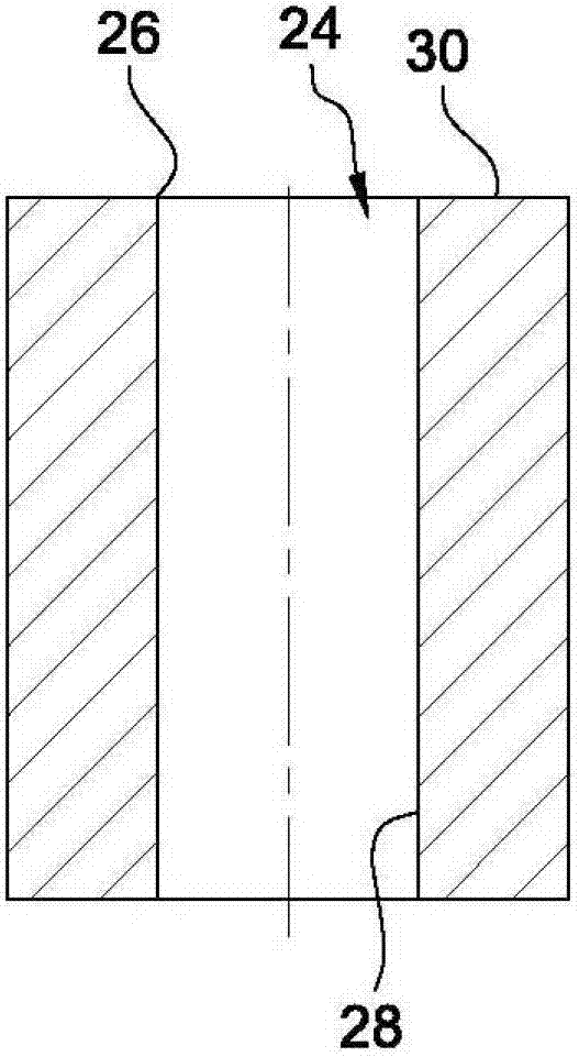
[0035] The rotor disk also has a flange 22 provided with a plurality of holes 24 evenly distributed around the axis of the rotor disk to facilitate fastening of the rotor disk 10 to an auxiliary structure. Each end of the hole 24 has an edge 26 (see figure 2 ).

[0036] In the traditional way, the edges formed by these edges are manually broken off by the operator, which means that a uniform and nea...


PUM


Abstract

The invention relates to an electrode for chamfering the corners of a workpiece by electrochemical machining, comprising at least one conductive region (62, 68) to be arranged facing a workpiece corner to be chamfered. Said electrode is characterized in that the conducting region (62, 68) has a shape complementary to that of the chamfered corner to be produced, and is arranged between a first part forming an insulating excessive thickness, and an insulating second part for positioning the conducting region such that it faces the corner to be chamfered.

Description

technical field [0001] The present invention relates to an electrode and also to a device for breaking edges on metal parts, such as those used in aviation. Background technique [0002] Many kinds of industrial parts have sharp edges, for example, the compressor of a turbomachine or the turbine rotor disk, which has a plurality of grooves distributed around its periphery for mounting blade roots, and the bottom of these grooves Intersects the upstream and downstream faces of the disk on multiple edges. There are also edges around the fixing holes and along the sides of the festoon of said flanges on the assembly flanges where the discs are assembled together. [0003] Such edges usually include burrs as a product of a specific shape (grooves, holes, cutouts, etc.) made on the part. For example, these burrs can be removed by mechanically breaking off the edges. [0004] For this purpose, it is known to use chamfers on the edges formed on the junction of the two surfaces. ...

Claims


Application Information

Patent Timeline
IPC IPC(8): B23H3/00B23H9/02
CPCB23H9/02B23H3/00
Inventor 尼古拉斯·巴蒂斯塔达米恩·赫比特恩安东尼·泰克西尔
Owner SN DETUDE & DE CONSTR DE MOTEURS DAVIATION S N E C M A
Why Eureka
Try Eureka