Optical device for photographing, optical system for photographing, and distance change detecting device

A technology of optical devices and optical sensors, which is applied in the field of optical systems for shooting and distance change detection devices, and can solve the problem of keeping the output of light reflectors roughly constant, etc.

Inactive Publication Date: 2016-07-06
SANKYO SEIKI MFG CO LTD
View PDF7 Cites 0 Cited by
  • Summary
  • Abstract
  • Description
  • Claims
  • Application Information

AI Technical Summary

Problems solved by technology

[0004] When using the photoreflector to detect the position of the movable module, the output current of the phototransistor (that is, the output of the photoreflector) can be used, but even if the distance between the movable module and the photoreflector is constant, it is difficult to reflect the light tor output remains roughly constant

Method used


Image

  • Optical device for photographing, optical system for photographing, and distance change detecting device
  • Optical device for photographing, optical system for photographing, and distance change detecting device
  • Optical device for photographing, optical system for photographing, and distance change detecting device

Examples


Embodiment Construction

[0052] Hereinafter, embodiments of the present invention will be described with reference to the drawings.

[0053] (Schematic structure of the optical device for shooting)

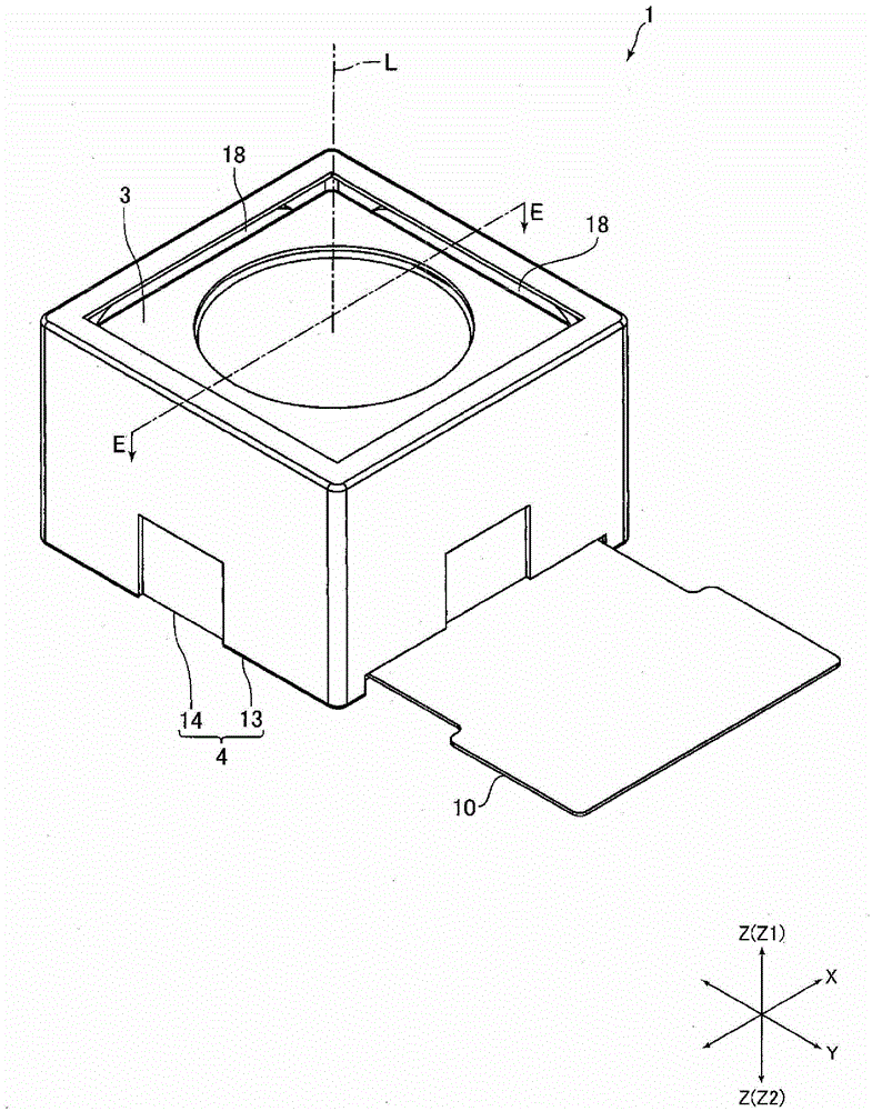
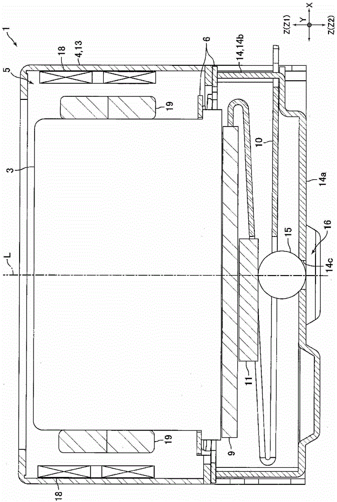
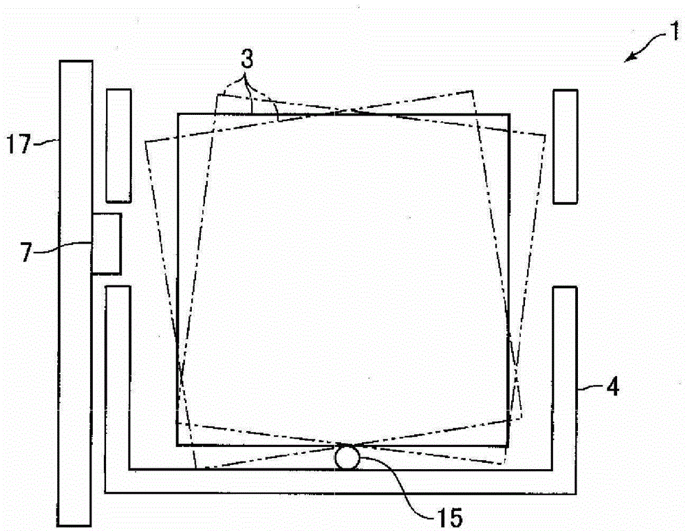
[0054] figure 1 It is a perspective view of the imaging optical device 1 according to the embodiment of the present invention. figure 2 yes figure 1 The sectional view of the E-E section of . image 3 yes means figure 1 It is a schematic diagram showing the arrangement relationship between the camera module 3 and the reflective optical sensor 7 in the photographing optical device 1 shown. Also, in the description below, as figure 1 As shown, let the three directions orthogonal to each other be the X direction, the Y direction, and the Z direction, respectively, let the X direction be the left-right direction, the Y direction be the front-rear direction, and the Z direction be the up-down direction. In addition, let the Z1 direction side be an "upper" side, and the Z2 direction side be a "lower" sid...


PUM


Abstract

The present invention provides an optical device for photographing capable of obtaining an output of a reflective optical sensor suppressing the influence of environmental changes and the like even when the distance between a camera module and the reflective optical sensor fluctuates. . The optical device for photographing includes a reflective optical sensor (7) with a light emitting element (21) and a light receiving element (22), a support body for fixing the reflective optical sensor (7), supported in a swingable manner by the support body, and A camera module (3) that reflects light from a light emitting element (21) toward a light receiving element (22), and a shake correction mechanism that swings the camera module (3) to correct shake. In this photographing optical device, an origin position voltage (V) is generated by an origin position voltage generation unit (24) that receives light when the camera module (3) is located at or near the origin position. The output voltage (Vout) of the element (22) utilizes a comparator (25) to compare the origin position voltage (V) with a reference voltage (Vref), and utilizes a variable current source (26) based on the voltage from the comparator (25) ) output signal to control the current supplied to the light emitting element (21).

Description

technical field [0001] The present invention relates to a photographing optical device including a shake correction function for correcting the shake of an optical image, and a photographing optical system including the photographing optical device. Furthermore, the present invention relates to a distance change detection device that detects a change in the relative distance between an object to be detected and a reflective optical sensor. Background technique [0002] In recent years, mobile devices such as mobile phones have been equipped with imaging optical devices. In the case of mobile devices, it is easy to shake hands when shooting. Therefore, the applicant of the present invention proposed an optical device for photographing capable of correcting hand shake during photographing (for example, refer to Patent Document 1). [0003] The imaging optical device described in Patent Document 1 includes: a movable module on which a lens and an imaging element are mounted; ...

Claims


Application Information

Patent Timeline
Patent Type & Authority Patents(China)
IPC IPC(8): G03B5/00H04N5/225H04N5/232
CPCG03B5/00G03B2205/0023G03B2205/0069H04N23/55H04N23/685G01B11/14G02B27/646
Inventor 内藤速人唐泽敏行小松亮二石原久宽
Owner SANKYO SEIKI MFG CO LTD
Why Eureka
Try Eureka