
Light emitting apparatus, backlight apparatus, and display apparatus

a backlight apparatus and light source technology, applied in the field of light emitting apparatus, backlight apparatus, and display apparatus, can solve the problems of complicated control circuit, inapplicability of backlights with a wide color gamut, and use of plurality of monochromatic light sources, so as to suppress individual differences in the manner of sensing colors, restrict the configuration of light source and control, and wide color gamut

Inactive Publication Date: 2015-07-30
CANON KK
View PDF9 Cites 2 Cited by
  • Summary
  • Abstract
  • Description
  • Claims
  • Application Information

AI Technical Summary

Benefits of technology

The patent is about a new technique for achieving a wide color range in a backlight using LED lights. The technique involves setting the spectral characteristic of a color component with a peak near 445 nm in the spectral characteristic of white light to have a broad and symmetric shape. This technique can be applied to LED lights that emit white light, but it is not suitable for backlights that use monochromatic LEDs for red, green, and blue to mix the colors to emit white light. This approach helps to achieve both a wide color range and reduce individual differences in the way colors are viewed. The light emitting apparatus described in the patent is designed to be simple and easy to control.

Problems solved by technology

The technique disclosed in Japanese Patent Application Laid-open No. 2011-40664 is limited to LED light sources that emit white light and is not applicable to backlights with a wide color gamut.
When the technique disclosed in Japanese Patent Application Laid-open No. 2011-40664 is applied to a backlight that uses monochromatic LEDs for red, green, and blue to mix the colors to emit white light, the use of the plurality of monochromatic light sources complicates a relevant control circuit.
The techniques allow a wide color gamut to be achieved but involve complicated control.
On the other hand, the inventors have found that the spectral characteristic of white light has a peak in each color component such as red, green, or blue and that a high color purity is likely to lead to individual differences in the manner of sensing colors.
Thus, disadvantageously, when a comparison is made between a wide-color-gamut backlight in which a defined white point is provided only by a white LED and a wide-color-gamut backlight in which the white point is provided by a red LED, a green LED, and a blue LED, individual differences in the manner of sensing colors are likely to occur in the latter wide-color-gamut backlight.
However, a configuration using one LED as a backlight light source has difficulty setting only the spectral characteristic of the blue color component, included in the spectral characteristic of white light, to be broad.
This leads to the need for at least light sources including a red LED, a green LED, a first blue LED, a second blue LED, resulting in to a complicated light source configuration or a complicated circuit configuration.
The need is also not economically advantageous.

Method used


Image

  • Light emitting apparatus, backlight apparatus, and display apparatus
  • Light emitting apparatus, backlight apparatus, and display apparatus
  • Light emitting apparatus, backlight apparatus, and display apparatus

Examples


embodiment 1

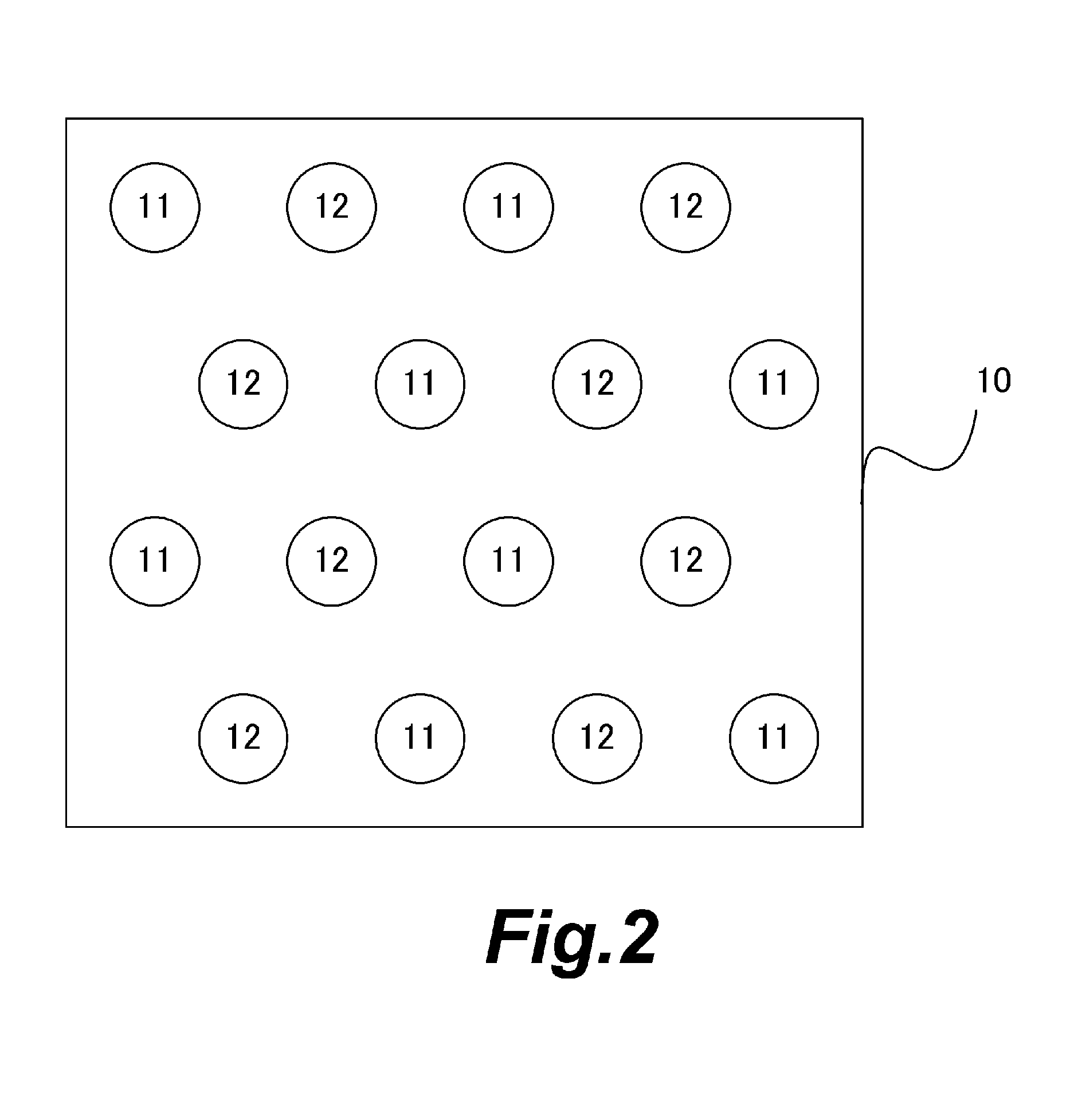
[0029]Embodiments of the present invention will be described with reference to the drawings. Embodiment 1 is characterized by a backlight including two types of LEDs as light sources to emit white light, in which the spectral characteristic of the white light has peaks for red, green, and blue and in which the spectral characteristic of blue has a broad shape that is linearly symmetric about a peak wavelength. Hereinafter, specific examples of implementation methods are explained.

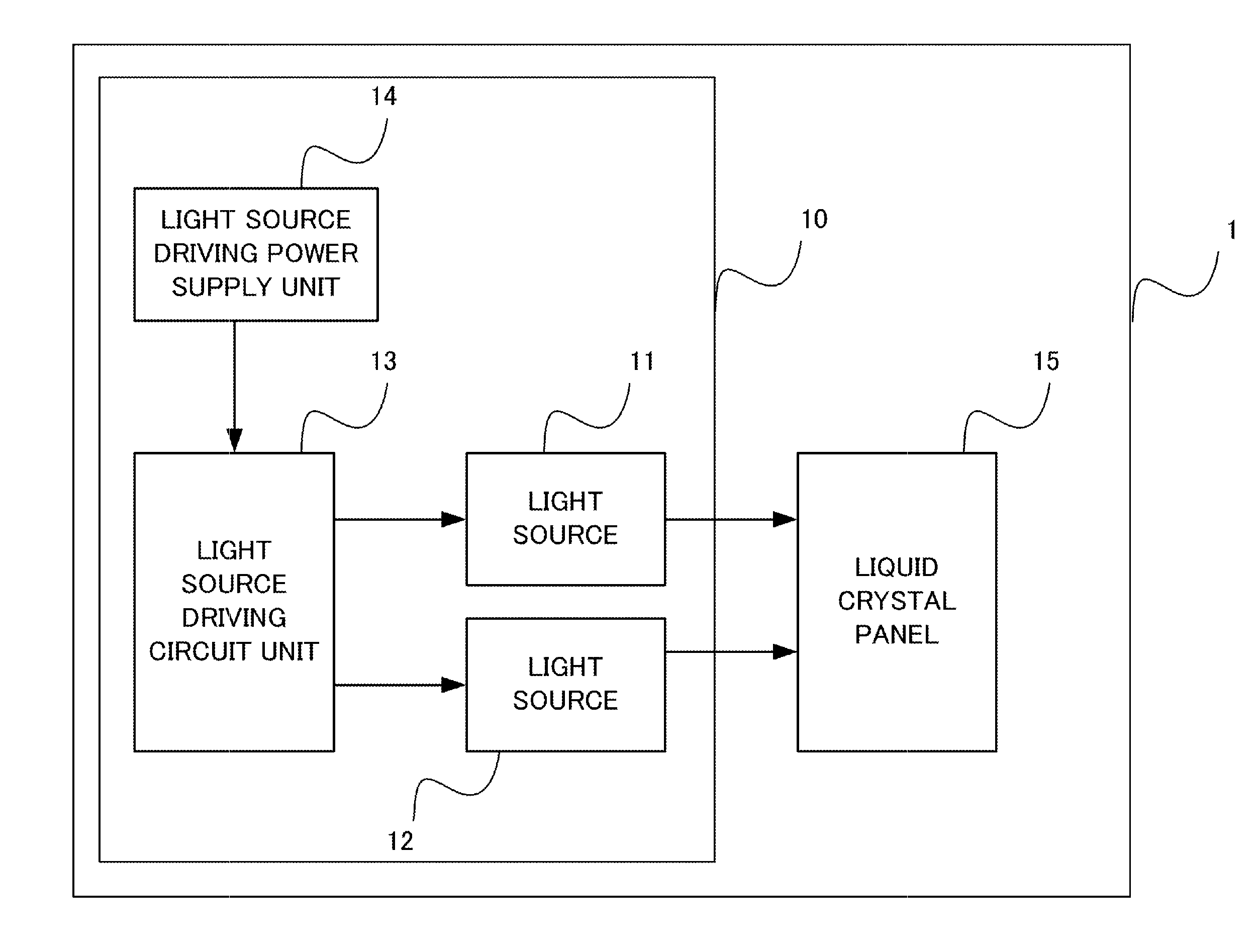
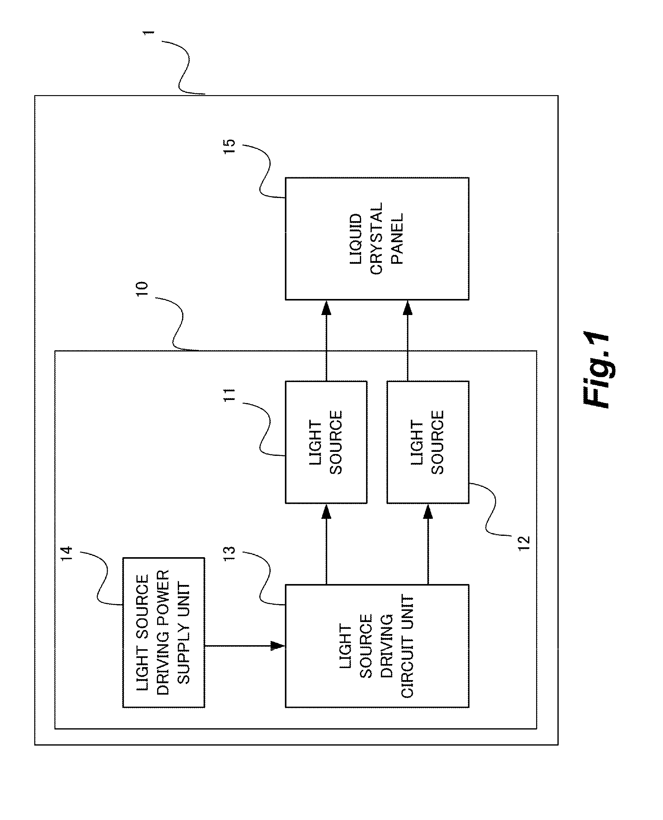
[0030]FIG. 1 is a block diagram depicting a general configuration of an image display apparatus according to Embodiment 1. An image display apparatus 1 has a backlight 10 and a liquid crystal panel 15. The backlight 10 has a light source 11 (first light source), a light source 12 (second light source), a light source driving circuit unit 13, and a light source driving power supply unit 14. Pixels in the liquid crystal panel 15 each have a blue color filter, a green color filter, and a red color filter. The ...

embodiment 2

[0042]FIG. 6 is a diagram depicting a spectral characteristic 20 of a light source 11 and a spectral characteristic 21 of a light source 12 in a backlight according to Embodiment 2 of the present invention.

[0043]Embodiment 2 is similar, in the configuration of the light sources, to but is different, in the spectral characteristic of each light source, from Embodiment 1. As depicted in FIG. 6, the light source 11 is a LED that emits ultraviolet light with a dominant wavelength within a predetermined fourth wavelength range. The LED excites blue light with a dominant wavelength within a first wavelength range. Furthermore, the light source 12 is a LED that emits blue light with a dominant wavelength within a second wavelength range. The LED excites green light with a peak within the second wavelength range and red light with a peak within the third wavelength range. The LED excites red light with a dominant wavelength within a third wavelength range.

[0044]In Embodiment 2, the light so...

embodiment 3

[0048]FIG. 8 is a diagram depicting a spectral characteristic 23 of a light source 11 and a spectral characteristic 24 of a light source 12 in a backlight according to Embodiment 3 of the present invention.

[0049]Embodiment 3 has a light source configuration similar to the light source configuration of Embodiment 1 but is different from Embodiment 1 in the spectral characteristic of each light source. As depicted in FIG. 8, the light source 11 is a LED that emits blue light with a dominant wavelength within a first wavelength range. The LED excites green light with a dominant wavelength within a second wavelength range and red light with a dominant wavelength within a third wavelength range. Furthermore, the light source 12 is a LED that emits blue light with a dominant wavelength within the first wavelength range.

[0050]In Embodiment 3, a peak wavelength within the first wavelength range of blue light emitted by the LED of the light source 11 is different from a peak wavelength withi...


PUM

PropertyMeasurementUnit
peak wavelengthaaaaaaaaaa
wavelength rangeaaaaaaaaaa

Abstract

A light emitting apparatus including a first and a second light source, wherein both light sources have spectral characteristics of blue light having an emission light peak within a first wavelength range, at least one of the light sources further has a spectral characteristic of at least one of green light having an emission light peak within a second wavelength range and red light having an emission light peak within a third wavelength range, and a composite spectral characteristic resulting from light emissions from the both light sources has peaks within the first, the second, and the third wavelength ranges, the peak within the first wavelength range has a larger half-value width than others, and the peak within the first wavelength range has a substantially symmetric shape about the peak wavelength.

Description

BACKGROUND OF THE INVENTION[0001]1. Field of the Invention[0002]The present invention relates to a light emitting apparatus, a backlight apparatus, and a display apparatus.[0003]2. Description of the Related Art[0004]In a backlight that uses a plurality of light sources such as light emitting diodes (hereinafter referred to as LEDs) which has a high color purity, color unevenness may occur in a surface of the backlight as a result of the adverse effect of a variation in wavelength among the light source.[0005]Japanese Patent Application Laid-open No. 2011-40664 describes a backlight including at least one first white light source with a peak wavelength within a wavelength range equal to or smaller than a predetermined target wavelength and at least one second light source with a peak wavelength within a wavelength range larger than the target wavelength, the first and second white light sources being disposed in proximity to each other. The spectral characteristic of the white light...

Claims


Application Information

Patent Timeline
Patent Type & Authority Applications(United States)
IPC IPC(8): G02F1/1335
CPCG02F1/133609G02F1/133617G02F1/133514G02F1/133603G09G2320/0242H05B45/20
Inventor MATSUURA, YASUHIRO
Owner CANON KK
Learn More