Light emitting device

a technology of light emitting devices and leds, which is applied in the direction of lighting and heating apparatuses, instruments, optical elements, etc., can solve the problems of viewing leds of different colors, and achieve the effect of complicated control circuits

Active Publication Date: 2013-07-23
KONINKLIJKE PHILIPS ELECTRONICS NV
View PDF13 Cites 3 Cited by
  • Summary
  • Abstract
  • Description
  • Claims
  • Application Information

AI Technical Summary

Benefits of technology

[0013]It is to be understood that a drive signal may be realized in the form of an applied voltage over the LED structure and / or a drive current through the LED structure. It may even be realized by applying a voltage across a certain region (or regions) and driving another region (or regions) with a current. This would, however, make the control circuits more complicated.
[0014]In embodiments of the light emitting device according to the present invention, light generated in the regions are coupled out to the sections through a first plane, being generally parallel to the plane of the LED structure. Mixed light comprises a mixture of light of a first color from the first section and light of a second color from the second section (the first color is different from the second color). Mixing of light occurs when light from one section passes through another adjacent section, i.e. mixing is achieved when the direction of light has a component in a direction parallel to the plane of the LED structure. The mixed light may exit (be coupled out from) the light emitting device through a second plane (a side of the light permeable device), which may be arranged at any angle with respect to the plane of the LED structure. This effect is mainly achieved by means of the at least partially reflecting layer. As a result, a substantial amount of the light from the first or second section is passing though the other section before exiting the light emitting device.
[0018]From the perspective of a viewer of the light emitting device according to embodiments of the present invention, the light from the two sections appears to come from substantially the same point. In this manner, the appearance of colored shadows is decreased. In addition a viewer looking directly at the light emitting device, or via a specular reflection, may not experience disturbing discolorations of the light emitting device, when the color point of the light emitting device according to embodiments is changed.
[0024]As an alternative, the first and second mirror may be arranged to be in parallel with each other. Advantageously, the shape of the sections may be rectangular. Such block shaped sections of, for example a phosphor ceramic material, may be easier to manufacture than more complicated shapes that may be needed for other arrangements of the mirrors.
[0029]In embodiments of the light emitting device according to the present invention, light from the first region may be of the same color as light from the second region. In this case, at least one of the sections of the light permeable device comprises a material that is adapted to convert the color of the light passing therethrough. See discussion above. An advantage may be that it is easier to manufacture an LED in which the individually controllable regions emit the same color.

Problems solved by technology

A disadvantage with such a system is that a viewer may see the LEDs of different colors, when looking into the lighting system.

Method used


Image

  • Light emitting device
  • Light emitting device
  • Light emitting device

Examples


Embodiment Construction

[0047]Throughout the following description similar reference numerals have been used to denote similar elements, parts, items or features, when applicable.

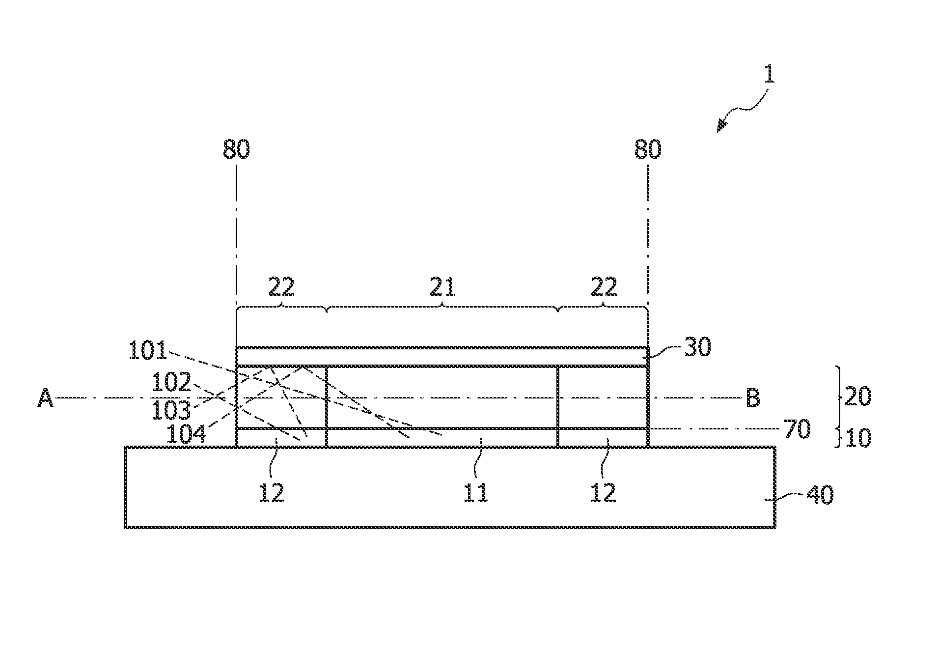
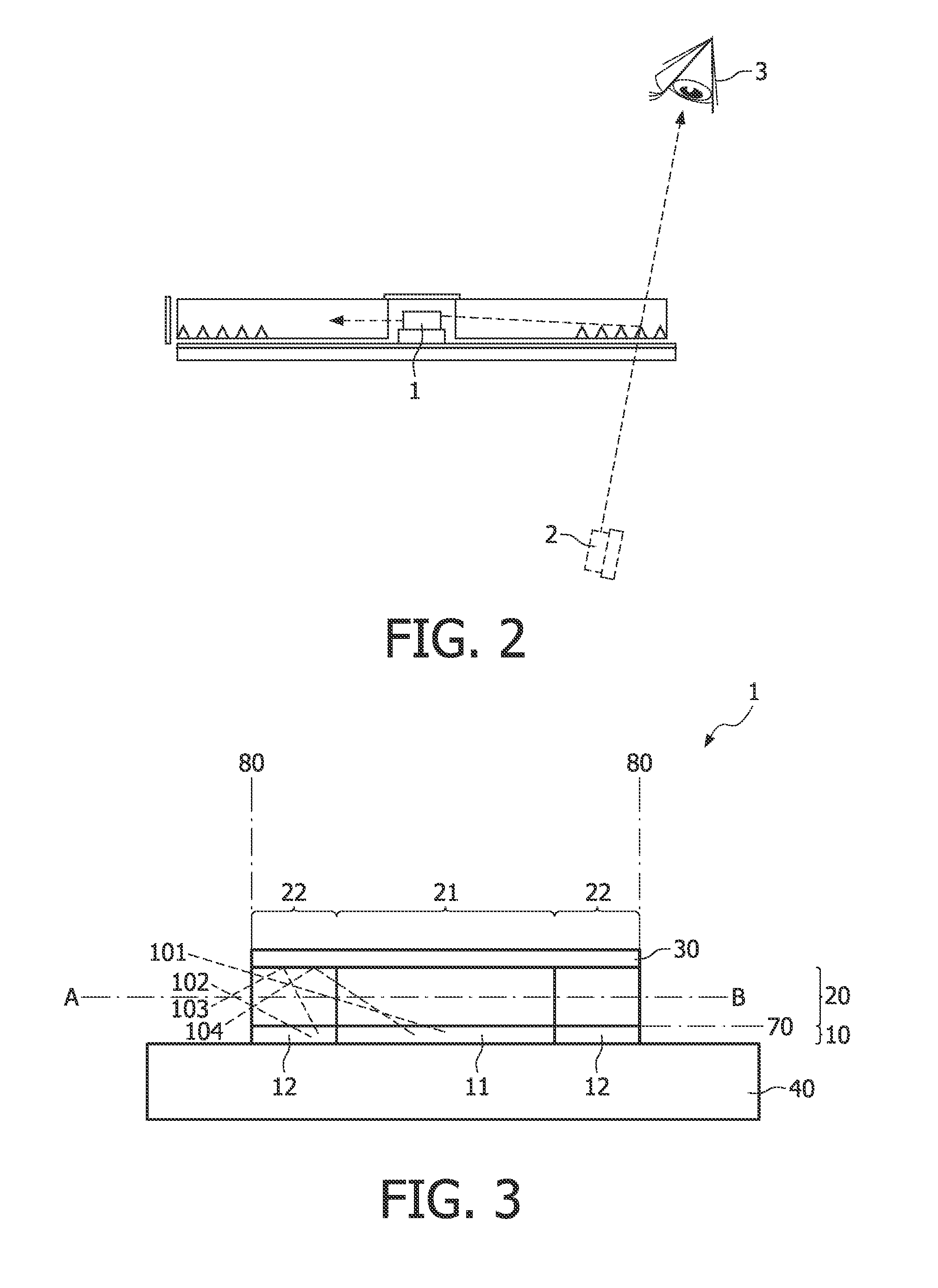
[0048]In FIG. 3, there is illustrated an example of the light emitting device according to an embodiment of the invention. The light emitting device 1 comprises a light emitting diode die 10 (LED die or LED structure), a phosphor ceramic tile 20 comprising two segments (or sections) 21, 22 and a reflector 30, disposed on each other in this order. Further, the light emitting device 1 is disposed on a substrate 40. The LED die 10 comprises two zones 11, 12 (or regions), which are individually controllable by application of a respective voltage to each respective zone 11, 12. In addition, each zone corresponds to and is aligned with a respective phosphor ceramic segment. The segments are of different types such as to be able to convert the color of light to two different colors. However, in other embodiments the segments may be of th...


PUM


Abstract

The present invention relates to a light emitting device (1) comprising a stack of a light emitting diode (LED) structure (10) and a light permeable device (20). The light permeable device (20) comprises at least a first and a second section (21, 22), color of light from said first and second section (21, 22) being different from each other. Further, the LED structure (10) comprises at least a first and a second region (11, 12) being individually controllable. The first and second region (11, 12) are associated with the first and second section (21, 22), respectively. The stack further comprises an at least partially reflecting layer (30) arranged such that light from the light permeable device (20), generated in the first and second region (11, 12), is to be mixed within the light emitting device (1).

Description

FIELD OF THE INVENTION[0001]The present invention relates to the field of light emitting devices, and more particularly to a light emitting device, comprising a stack of a light emitting diode structure and a light permeable device.BACKGROUND OF THE INVENTION[0002]Use of light emitting diodes (LEDs) is widely spread. For example, LEDs are used as light sources in thin, large area lighting systems, automotive lights, signs and backlight illumination for display devices and more. In many applications, it is desired to be able to control the color point of the light output. This may be achieved by the use of multiple individually controllable LEDs of different colors. In this manner, the amount of, for example, red, green and blue light may be controlled such as to obtain a desired color point of the total light emission from a device, comprising LEDs of different colors.[0003]In WO 2007 / 034367 A1, there is disclosed a variable color light emitting device, comprising a light emitting d...

Claims


Application Information

Patent Timeline
Patent Type & Authority Patents(United States)
IPC IPC(8): H01L33/00H01L33/50H01L33/60
CPCG02B6/0078H01L27/15G02B6/0038H01L33/504H01L2924/0002H01L33/60H01L2924/00
Inventor WILLEMSEN, OSCAR HENDRIKUSVISSENBERG, MICHEL CORNELIS JOSEPHUS MARIEVAN GORKOM, RAMON PASCAL
Owner KONINKLIJKE PHILIPS ELECTRONICS NV
Why Eureka
Try Eureka