Asynchronous FIFO circuit

a fifo and circuit technology, applied in the field of asynchronous firstin firstout (fifo) circuits, can solve the problems of complex control circuits, different transfer timings between bits, and increased control complexity, and achieve the effect of reducing the latency from writing to reading and not complicated control circuits

Active Publication Date: 2021-12-21
NEC PLATFORMS LTD
View PDF11 Cites 0 Cited by
  • Summary
  • Abstract
  • Description
  • Claims
  • Application Information

AI Technical Summary

Benefits of technology

[0005]In an asynchronous FIFO circuit including the above-described circuit that determines full / empty, when it is full with data, a data queue is generated. Therefore, a buffer is required at an input part of a transfer circuit, causing the control circuit to be complicated. Moreover, when the data width is wide, there is a case where the transfer timing differs between bits due to physical constraint. This makes the control more complicated, and a time is needed time until the entire data is prepared.
[0007]Therefore, an object of the present invention is to provide an asynchronous FIFO circuit capable of solving the above-described problems, that is, complicated control and an increase in the latency from writing to reading.
[0027]Since the present invention is configured as described above, the present invention can provide an asynchronous FIFO circuit in which control is not complicated and the latency from writing to reading can be reduced.

Problems solved by technology

Therefore, a buffer is required at an input part of a transfer circuit, causing the control circuit to be complicated.
Moreover, when the data width is wide, there is a case where the transfer timing differs between bits due to physical constraint.
This makes the control more complicated, and a time is needed time until the entire data is prepared.
This may cause a problem of an increase in the latency from writing to reading.

Method used


Image

  • Asynchronous FIFO circuit
  • Asynchronous FIFO circuit
  • Asynchronous FIFO circuit

Examples


first exemplary embodiment

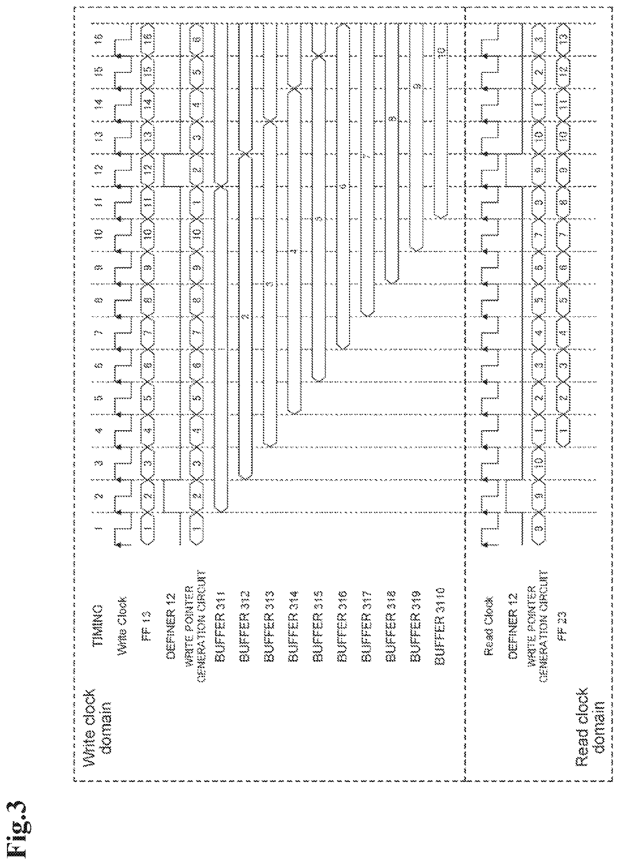
[0034]A first exemplary embodiment of the present invention will be described with reference to FIGS. 1 to 5. FIGS. 1 and 2 are diagrams for explaining a configuration of an asynchronous FIFO circuit. FIG. 3 is a diagram for explaining an operation of the asynchronous FIFO circuit. FIGS. 4 and 5 are diagrams for explaining effects of the present invention.

[Configuration]

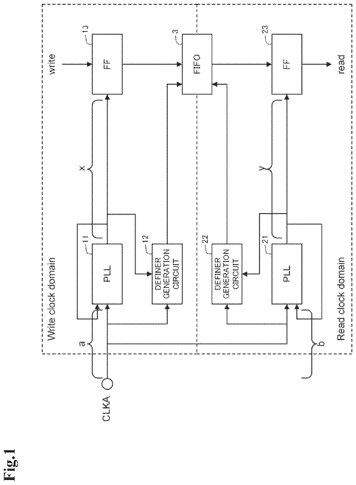
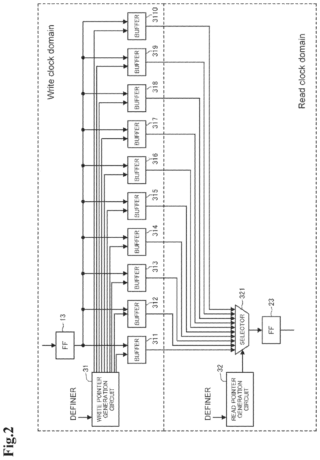
[0035]As illustrated in FIG. 1, an asynchronous FIFO circuit of the present invention includes, in the write clock domain, a phase locked loop (PLL) 11, a definer generation circuit 12, and a flip-flop (FF) 13. The asynchronous FIFO circuit also includes, in the read clock domain, a PLL 21, a definer generation circuit 22, and a flip-flop (FF) 23. The asynchronous FIFO circuit also includes a FIFO (first-in, first-out) 3 for data transfer. The FIFO belongs to both the write clock domain and the read clock domain.

[0036]The PLL 11 (write clock generation unit) in the write clock domain generates a write clock to be use...

second exemplary embodiment

[0065]Next, a second exemplary embodiment of the present invention will be described with reference to FIG. 6. FIG. 6 is a block diagram illustrating a configuration of an asynchronous FIFO circuit according to the present embodiment. Note that the present embodiment shows the outline of the configuration of the asynchronous FIFO described in the first exemplary embodiment.

[0066]As illustrated in FIG. 6, an asynchronous FIFO circuit 100 of the present embodiment includes

[0067]a write clock generation unit 110 that generates, from an input clock, a write clock to be used in write processing,

[0068]a read clock generation unit 120 that generates, from the input clock, a read clock to be used in read processing,

[0069]a write control signal generation unit 130 that generates a write control signal for controlling data write timing, in synchronization with the write clock,

[0070]a read control signal generation unit 140 that generates a read control signal for controlling data read timing,...


PUM


Abstract

An asynchronous FIFO circuit of the present invention generates a write clock and a read clock from the same input clock, and generates a write control signal in synchronization with the write clock and a read control signal in synchronization with the read clock. The asynchronous FIFO circuit includes a data read-write unit having a plurality of data holding units. The data read-write unit writes data into one of the data holding units for each write clock on the basis of the write control signal, and reads data from one of the data holding units for each read clock on the basis of the read control signal.

Description

[0001]This application is a National Stage Entry of PCT / JP2018 / 032935 filed on Sep. 5, 2018, which claims priority from Japanese Patent Application 2017-202859 filed on Oct. 19, 2017, the contents of all of which are incorporated herein by reference, in their entirety.TECHNICAL FIELD[0002]The present invention relates to an asynchronous first-in first-out (FIFO) circuit, and in particular, to an asynchronous FIFO circuit not requiring a full / empty determination circuit.BACKGROUND ART[0003]In the case of processing consecutive data such as a memory access, a circuit that determines full / empty may be provided as described in Patent Literature 1.[0004]Patent Literature 1: JP 3013800 BSUMMARY[0005]In an asynchronous FIFO circuit including the above-described circuit that determines full / empty, when it is full with data, a data queue is generated. Therefore, a buffer is required at an input part of a transfer circuit, causing the control circuit to be complicated. Moreover, when the data...

Claims


Application Information

Patent Timeline
Patent Type & Authority Patents(United States)
IPC IPC(8): G11C7/22G11C7/10
CPCG11C7/222G11C7/1057G11C7/1063G11C7/1084G11C7/1096G06F5/06
Inventor FUJIHARA, KOKI
Owner NEC PLATFORMS LTD
Why Eureka
Try Eureka