Color Liquid Crystal Display Apparatus

a liquid crystal display and liquid crystal technology, applied in the direction of instruments, discharge tubes luminescnet screens, static indicating devices, etc., can solve the problems of liquid crystal display panels, color filters, described above, poor color purity, etc., to achieve and a wide color range.

Inactive Publication Date: 2007-11-01
SONY CORP
View PDF4 Cites 32 Cited by
  • Summary
  • Abstract
  • Description
  • Claims
  • Application Information

AI Technical Summary

Benefits of technology

[0017] When light emitting diodes of three prime colors are used as light sources, the color reproducing range depends mainly on the wavelength bands of the light emitting diodes. If desired to enlarge the color gamut further, it is also crucial to optimize the transmission wavelength bands of the color filter, provided on the color liquid crystal display panel, in order to cope with the wavelength bands of the light emitting diodes. That is, the color purity of a picture displayed on a color liquid crystal display apparatus is appreciably changed by the matching between the light emitting diodes, used as light sources, and the color filter, such as to affect the color reproducing range appreciably. Hence, the optimum designing of the light emitting diodes, as light source, and the color filter, represents a crucial factor for achieving the wide color gamut.
[0018] In view of the above problems, it is an object of the present invention to provide a color liquid crystal display apparatus of the backlight system in which characteristics of the light emitting diode and the color filter may be optimized to allow for a broader color gamut.

Problems solved by technology

For example, if a camera has captured the color information accurately, but a display demonstrates the color information only inappropriately, color reproduction performance of the system on the whole is deteriorated.
Hence, there is a problem that the color reproduced by the combination of the backlight device, having such CCFL, emitting the light of three wavelength ranges, as light source, and the color liquid crystal display panel, having the color filter, described above, is rather poor in color purity.
That is, the former color reproducing range may not be said to cope sufficiently with the current television broadcasting.
On the other hand, there is a fear that the CCFL, containing mercury in the phosphorescent tube, may have an ill effect on the environment.

Method used


Image

  • Color Liquid Crystal Display Apparatus
  • Color Liquid Crystal Display Apparatus
  • Color Liquid Crystal Display Apparatus

Examples


example 1

[0137] Example in Which the Peak Wavelength λpb of the Blue Light Emitting Diode 21B is Shifted Towards the Short Wavelength Side

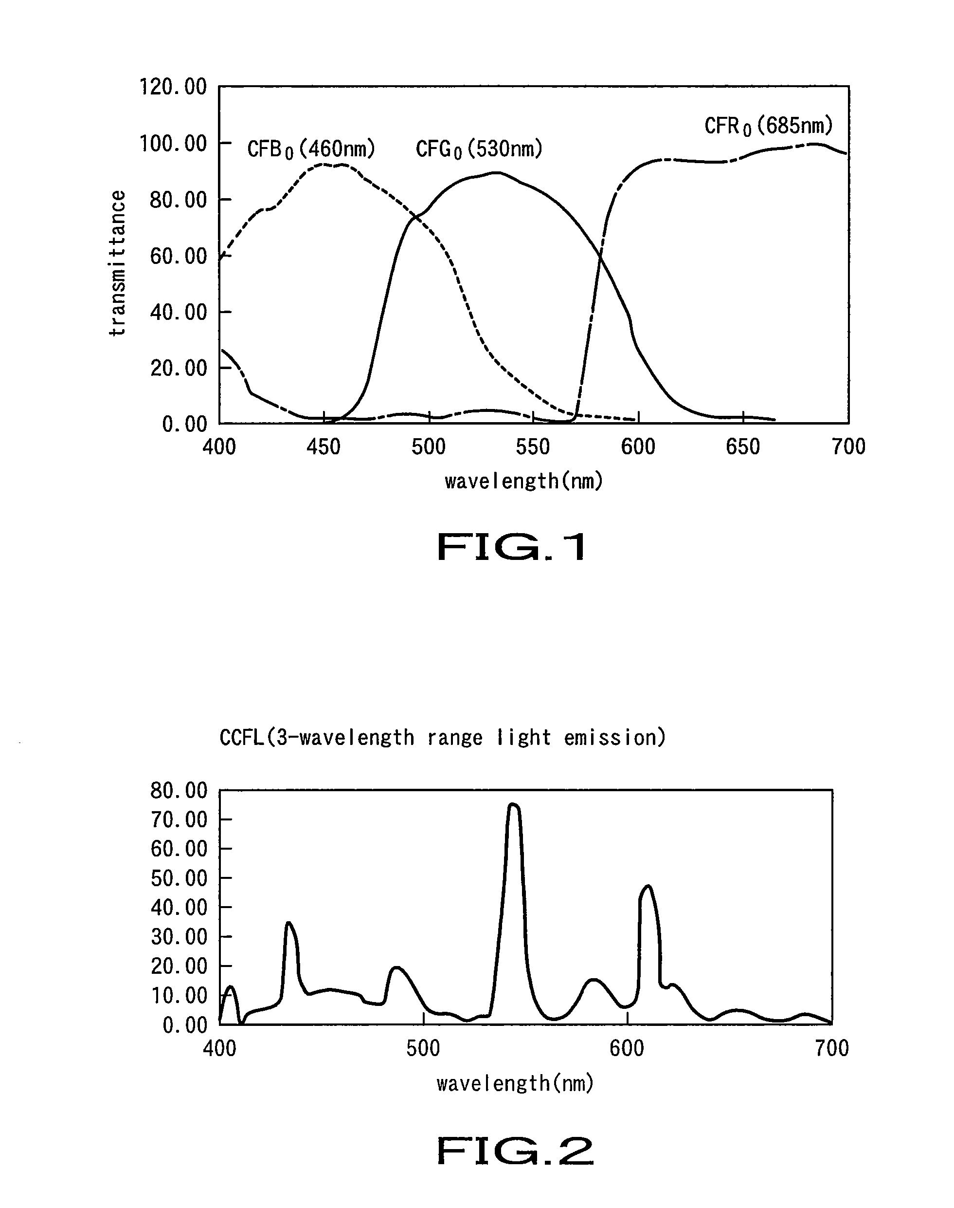
[0138] As described above, in case the peak wavelength λpb of the blue light emitting diode 21B is shifted towards the short wavelength side, the crossing point with the transmission wavelength band of the green filter CFG is lowered, and hence the color reproducing range becomes broader.

[0139] However, the red filter CFR exhibiting a certain value of transmittance in a wavelength region F in the vicinity of 400 nm to 450 nm of the wavelength of the transmission wavelength band of the blue filter CFB, as shown in FIG. 12, is obstructive in raising color purity or in providing for a broader color gamut. For example, if the amount of light transmission of the red filter CFR is gradually increased from 450 nm towards 400 nm until the red filter has the transmittance of approximately 12% at the wavelength of 400 nm, the respective colors are deteriorated in ...

example 2

[0163] Example in Which the Peak Wavelength λpr of the Red Light Emitting Diode 21R is Shifted Towards the Long Wavelength Side

[0164] As described above, in case the peak wavelength λpr of the red light emitting diode 21R is shifted towards the long wavelength side, the crossing point of the spectral curve with the transmission wavelength band of the green filter CFG is lowered, and hence the color reproducing range becomes broader.

[0165] Thus, as shown in FIG. 29, the peak wavelength λpr of the red light emitting diode 21R is shifted towards the long wavelength side from 640 nm by 5 nm, that is, to 645 nm, for the color filter 19B. FIG. 30 shows how the NTSC ratio is changed with changes in the peak wavelength λpr of the red light emitting diode 21R. It is seen from FIG. 30 that the NTSC ratio has been changed to 116% from 115%, that is, the NTSC ratio has been improved by 1%, for the case in which, with the use of the color filter 19B, the peak wavelength λpb of the blue light e...

example 3

Example in Which the Half-Value Width of the Green Filter CFG is Made Narrower to Make the Transmission Wavelength Band Narrower

[0169] As described above, in case the transmission wavelength band of the green filter CFG is made narrower, the crossing points of the transmission wavelength band with the spectral curves of the red light emitting diode 21R and the green light emitting diode 21G, are lowered, and hence the color reproducing range becomes broader.

[0170] That is, the half-value width Fhwg of the green filter CFG is narrowed by equal amounts from 100 nm to 80 nm from the long wavelength side and from the short wavelength side, as shown in FIG. 35. In the description to follow, the color filter, in which the half-value width Fhwg of the green filter CFG of the color filter 19B is narrowed by equal amounts from the long wavelength side and from the short wavelength side such that 80 nm≦Fhwg≦100 nm, is termed a color filter 19C.

[0171]FIG. 36 shows the manner in which the N...


PUM

PropertyMeasurementUnit
peak wavelength λpbaaaaaaaaaa

Abstract

Disclosed is a color liquid display (LCD) employing a transmissive color liquid display panel. The display includes a complementary color light emitting diode, which is one of a cyan light emitting diode (21C), emitting cyan light, a yellow light emitting diode, emitting yellow light, and a magenta light emitting diode, emitting magenta light, in addition to light emitting diodes emitting three prime colors, as a light source. The display also includes a complementary color filter, having at least one of a cyan filter CFC having a transmission wavelength range corresponding to the cyan light, a yellow filter CFY having a transmission wavelength range corresponding to the yellow light and a magenta filter CFM having a transmission wavelength range corresponding to the magenta light, in addition to a tristimulus color filer, as a color filter (19).

Description

TECHNICAL FIELD [0001] This invention relates to a color liquid crystal display (LCD) apparatus with which the color gamut can be made broader to assure more faithful color reproducing performance. [0002] The present application claims priority rights on the basis of the Japanese Patent Application 2004-294242 filed in Japan on Oct. 6, 2004. The contents of these Patent Applications are to be incorporated by reference in the present application. BACKGROUND ART [0003] Among standard color spaces for computer display, there is the sRGB standard prescribed by IEC (International Electro-technical Commission). This standard gives a definition on the relationship between a video signal RGB and the calorimetric values by having chromaticity points of three prime colors of red (R), green (G) and blue (B) coincide with the colorimetric parameters of Rec.709 recommended by ITU-R (International Telecommunication Union Radio communication). In a display apparatus, complying with this sRGB stand...

Claims


Application Information

Patent Timeline
Patent Type & Authority Applications(United States)
IPC IPC(8): G02F1/1335
CPCG02B5/223G02B27/1053G02F1/133514G09G2340/06G02F1/133609G02F2201/52G09G3/3413G02F1/133603G02B5/20G02F1/1335
Inventor HAGA, SHUICHIKAKINUMA, KOICHIRONAKATSUE, TAKEHIROMATSUMOTO, TATSUHIKO
Owner SONY CORP
Why Eureka
Try Eureka