Device for push-of-war and tug-of-war competitions

A push-pull rod and carriage technology, applied in sports accessories, stilts, gymnastics equipment and other directions, can solve the problems of the opponent's athlete's loss of balance, athlete's sports injury, fall, etc., to improve competition facilities, enhance participation enthusiasm, and increase competition interest. Effect

Inactive Publication Date: 2013-05-08
YANSHAN UNIV
View PDF5 Cites 8 Cited by
  • Summary
  • Abstract
  • Description
  • Claims
  • Application Information

AI Technical Summary

Problems solved by technology

The disadvantage of such round stake competition is that if one of the athletes of both sides pushes hard in the side direction during the competition, the opponent's athlete will lose balance or fall down.
This makes the result of the game more accidental, which will not only make the game lack of fairness, but also cause sports injuries to the athletes; the equipment usually used in the tug-of-war game is a rope with a marker in the middle. During the game, the athletes of the two teams hold the tug-of-war rope pull on both sides
The problems existing in the tug-of-war competition with this equipment are: ①There are errors in judging the results of the game by the referee’s eyes, such as whether the center marker is at the center point before the tug-of-war competition starts, and whether the center marker reaches the boundary line during the game. There are errors; ②One player Suddenly letting go of the tug-of-war rope will cause many athletes on the other side to fall down and cause sports injuries; ③ One athlete pulls suddenly to the side, which will cause the other athlete’s center of gravity to lose balance or fall and be injured, thus affecting the competition performance

Method used


Image

  • Device for push-of-war and tug-of-war competitions

Examples


Embodiment Construction

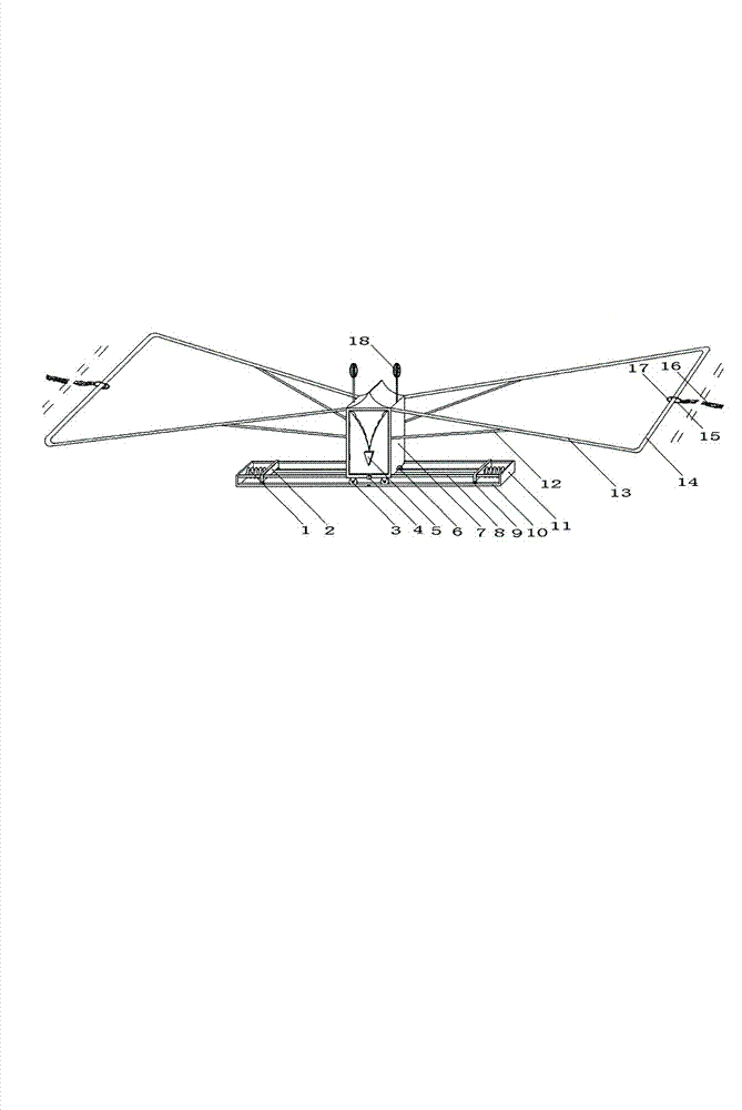
[0012] exist figure 1 In the schematic diagram of the device for pushing and tug-of-war competitions shown, the main structure of the device is composed of a rail car and an underframe. Wherein, the main structure of the rail car includes a compartment 7, the left and right sides of the compartment are respectively fixedly connected with four push-pull rods 13, and the other ends of the four push-pull rods are respectively fixedly connected with the two ends of the two handle bars 14, forming a symmetrically arranged isosceles Trapezoidal, one end of four struts 12 is connected with compartment 7, and the other end is connected with push-pull rod. The middle parts of the two handles are respectively provided with hanging rings 17, and the two hanging rings are respectively connected with two hooks 15, and the hooks are connected with the tug-of-war rope 16 through fixing parts. 4. There are pressure switches 6 on both sides of the lower part of the carriage, batteries are ins...


PUM


Abstract

The invention discloses a device for push-of-war and tug-of-war competitions. A major structure of the device comprises a rail car and a chassis part. A major structure of the rail car is fixedly connected by a carriage and four push-pull rods. The other ends of the four push-pull rods are respectively fixedly connected with two holding rods to form a symmetrically arranged isosceles trapezoid. Four supporting rods are taken as a support, four wheels are arranged at the bottom of the carriage, pressure switches are disposed on both sides of the lower portion of the carriage, and indicating lamps are arranged on both sides of the upper end of the carriage. The chassis part is substantially composed of a rail, a vertical plate, an inner casing pipe, a baffle, springs and casters in a connected mode. The pressure switches are started when the carriage and the baffle are contacted with each other, and then the indicating lamps are lightened. By means of the device, the defect that sport injuries are caused to players on one side when players on the other side exert strength in the side direction or loosen hands suddenly can be effectively avoided, competitions can be fair and reasonable, a referee can give more scientific and accurate judging results, and the application of the device can be of actual significance to improving results of push-of-war and tug-of-war competitions.

Description

technical field [0001] The invention relates to a sports competition apparatus, in particular to an apparatus used in pushing and tug-of-war competitions. Background technique [0002] River pushing competition is a form of competition in which two or more athletes use related equipment to push equipment against each other within the specified competition area. At present, there is no prescribed competition equipment for the river pushing competition. In the game competition, round wooden stakes are usually used as the equipment for pushing the river. During the game, players from both sides push each other with round wooden stakes. The disadvantage of such push round stake competition is: if one of the athletes of both sides pushes hard in the side direction during the competition, it will make the opponent's athlete lose balance or fall down. This makes the result of the game more accidental, which will not only make the game lack of fairness, but also cause sports injur...

Claims


Application Information

Patent Timeline
Patent Type & Authority Applications(China)
IPC IPC(8): A63B26/00A63B71/06
Inventor 张兴海
Owner YANSHAN UNIV
Why Eureka
Try Eureka