
Horizontal impinging stream reactor

A technology of impinging flow reactor and reactor shell, which is applied in the chemical industry, can solve the problems of reducing the service life of the reactor, the long time of material back-mixing, and affecting the mixing efficiency, etc., and achieves easy operation and maintenance, high-efficiency mixing performance, and improved The effect of production efficiency

Inactive Publication Date: 2015-05-20
WUHAN INSTITUTE OF TECHNOLOGY
View PDF6 Cites 0 Cited by
  • Summary
  • Abstract
  • Description
  • Claims
  • Application Information

AI Technical Summary

Problems solved by technology

At present, most impinging flow reactors are equipped with a propeller structure in the guide tube or use a power source to accelerate the fluid and collide with each other. Although the reactor with the propeller structure can achieve the purpose of mixing and strengthening, the motor shaft installed with the propeller It is a cantilever structure, which can easily lead to instability and easy damage of the whole device, thus reducing the service life of the reactor. Using the power source, such as through the action of a pump, to give the material a certain initial velocity, so that the axial direction impacts each other to strengthen the mixing effect. , but because the inlet of the circulation pipeline connected to the pump is located at the bottom of the reactor, the material back-mixing time after impact mixing is too long, which affects the mixing efficiency

Method used


Image

  • Horizontal impinging stream reactor
  • Horizontal impinging stream reactor

Examples


Embodiment Construction

[0016] In order to make the object, technical solution and advantages of the present invention clearer, the present invention will be further described in detail below in conjunction with the accompanying drawings and embodiments. It should be understood that the specific embodiments described here are only used to explain the present invention, not to limit the present invention.

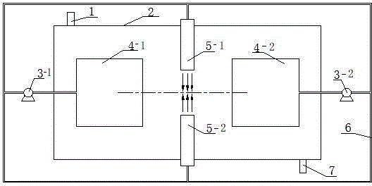
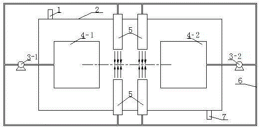
[0017] like figure 1 As shown, the horizontal impinging flow reactor includes a reactor shell 2, a feed pipe 1, a discharge pipe 7, a first draft tube 4-1, a second draft tube 4-2, and a first pump 5-1 , the second pump 5-2 and the circulation pipeline 6. The shape of the reactor shell 2 is cylindrical and placed horizontally. The feed pipe 1 and the discharge pipe 7 are arranged on the reactor shell 2. The feed pipe 1 is arranged on the upper end of the reactor shell 2. A pipe 7 is provided at the lower end of the reactor shell 2 . In the reactor shell 2, a first flow guide cylinder 4-1 and a s...


PUM


Abstract

The invention discloses a horizontal impinging stream reactor which comprises a reactor shell, a feeding pipe, a discharge pipe, a pair of guide cylinders, a pump and a circulation pipeline, wherein the feeding pipe and the discharge pipe are arranged on the reactor shell, the pair of guide cylinders is horizontally, coaxially and symmetrically arranged in the reactor shell, the guide cylinders are used for guiding a material so that the material can be sucked by the pump, inlets of the guide cylinders are oppositely formed and spaced according to a first setting distance to form a material suction area, and outlets of the guide cylinders are respectively communicated with an inlet of the pump via the circulation pipeline. A pair of nozzles is coaxially and symmetrically arranged on the reactor shell between the guide cylinders along the direction vertical to the axial direction of the guide cylinders, outlets of the nozzles are oppositely formed and spaced according to a second setting distance to form a material opposite-impact area, and inlets of the nozzles are communicated with an outlet of the pump via the circulation pipeline. The horizontal impinging stream reactor disclosed by the invention not only improves the mixing efficiency of the material, but also improves the stability and the continuity of the reactor, reduces the back mixing time, and has a simple structure and a good economic performance.

Description

technical field [0001] The invention relates to a reactor in the field of chemical industry, in particular to a circulating impingement flow reactor used in a liquid phase reaction process. Background technique [0002] The impinging flow reactor is a new type of reactor used in the chemical industry. It uses two high-speed fluids to collide with each other to increase the heat transfer and mass transfer rate. It has been successfully used in chemical processes such as absorption, mixing, heat transfer and crystallization. . At present, most impinging flow reactors are equipped with a propeller structure in the guide tube or use a power source to accelerate the fluid and collide with each other. Although the reactor with the propeller structure can achieve the purpose of mixing and strengthening, the motor shaft installed with the propeller It is a cantilever structure, which can easily lead to instability and easy damage of the whole device, thus reducing the service lif...

Claims


Application Information

Patent Timeline
IPC IPC(8): B01J19/26
Inventor 杨侠余蓓罗燕郭钊
Owner WUHAN INSTITUTE OF TECHNOLOGY
Learn More