
Cleaning robot

A robot and clean technology, applied in the direction of manipulators, program-controlled manipulators, manufacturing tools, etc., can solve the problem that the air flow may not be smooth, and achieve the effect of smooth work

Active Publication Date: 2013-05-08
YAMAHA MOTOR CO LTD
View PDF8 Cites 6 Cited by
  • Summary
  • Abstract
  • Description
  • Claims
  • Application Information

AI Technical Summary

Problems solved by technology

Therefore, the air flow in the rotating arm is not necessarily smooth, and there is room for improvement in making the working shaft work at a higher speed and more smoothly

Method used


Image

  • Cleaning robot
  • Cleaning robot
  • Cleaning robot

Examples


Embodiment Construction

[0015] Hereinafter, embodiments of the present invention will be described with reference to the drawings. In order to make the description easier to understand, the same reference numerals are attached to the same structural elements as much as possible in the drawings, and repeated descriptions are omitted.

[0016] In this embodiment, the cleaning robot according to the present invention will be described by taking an articulated robot as an example, but the applicable range of the cleaning robot according to the present invention is not limited thereto. The present invention can also be applied to other types of robots, such as an orthogonal robot, within the range in which the technical idea around the working axis described later can be applied.

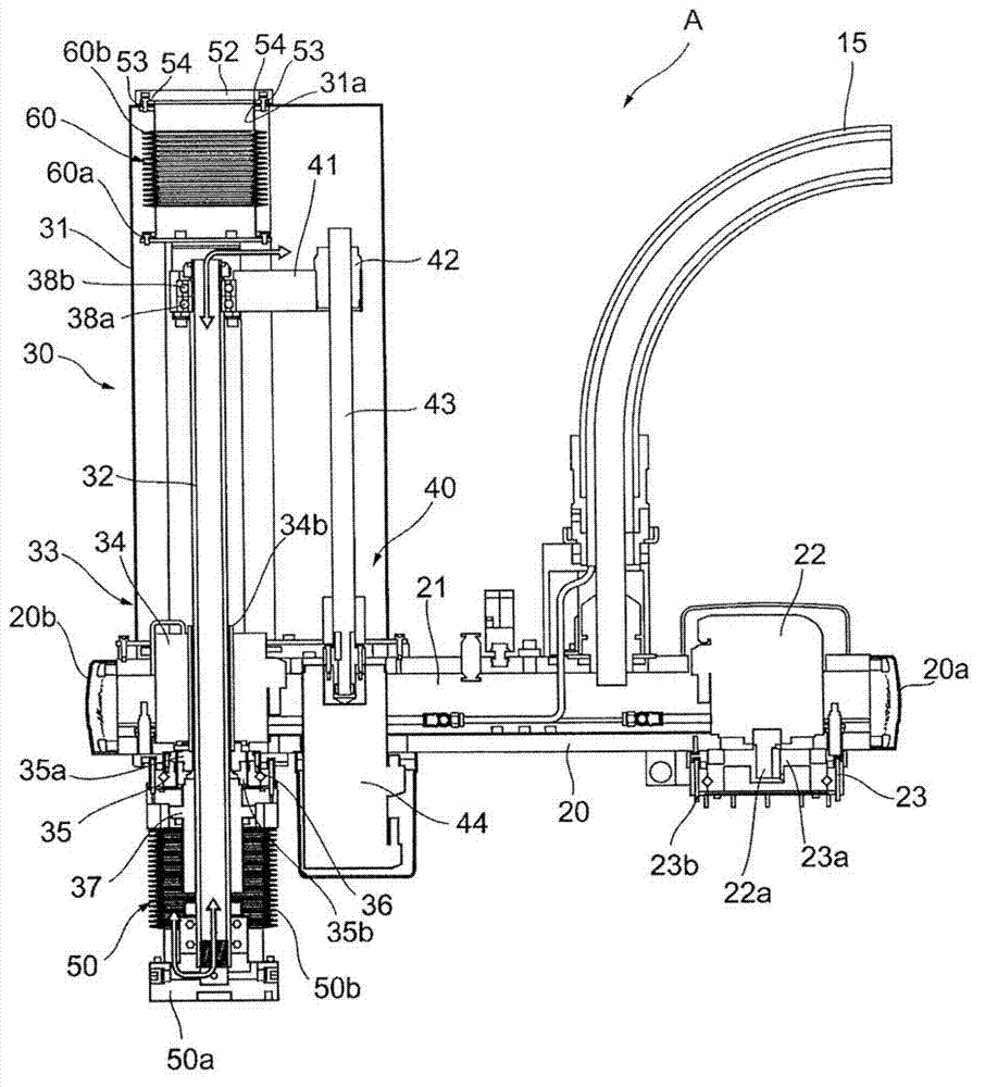
[0017] refer to figure 1 The articulated robot according to this embodiment will be described. figure 1 It is a schematic cross-sectional view showing the second arm 20 of the articulated robot A and the elevating and rotatin...


PUM


Abstract

The cleaning robot comprises a work shaft, a driving mechanism, a cover portion and a capacity maintaining mechanism, wherein the work shaft has a first end portion and a second end portion; the driving mechanism drives the work shaft to go forward and backward; the cover portion covers the work shaft and the driving mechanism; the capacity maintaining mechanism has a first extension portion which, in a state of covering an extension portion of the work shaft, is fixed between the first end portion of the work shaft and the cover portion, and a second extension portion which is positioned on an inner side of the cover portion and is fixed between the second end portion of the work shaft and the cover portion, and keeps certain capacity of space defined by the cover portion, every inner surfaces of the first extension portion and outer surfaces of the second extension portion. As the first end portion of the work shaft extends from the cover portion based on the work of the driving mechanism, the first extension portion extends relative to the cover portion toward an outer side of the shaft direction of the work shaft; as the first end portion of the work shaft extends from the cover portion, the second extension portion which is on the inner side of the cover portion, extends in the same extension direction of the first extension portion. In this way, the cleaning robot enables the work shaft to operate relatively quickly and smoothly.

Description

technical field [0001] The present invention relates to a clean robot having a function of preventing dust and the like generated inside the robot from being released to the outside. Background technique [0002] There is known a cleaning robot that is configured not to release dust or the like generated at least inside the device for use in mounting electronic components or the like. This cleaning robot can prevent external dust or water droplets from entering the device, or prevent dust or oil droplets inside the device from flying to the outside. It is a known cleaning robot as a dust-proof and anti-drip specification or a clean room specification robot. [0003] As such a cleaning robot, for example, a cleaning robot described in Japanese Patent Laid-Open Publication No. 2011-101907 (hereinafter referred to as Patent Document 1) is known. The cleaning robot disclosed in this gazette is an articulated robot (SCARA robot) having a rotating arm. The rotating arm is provid...

Claims


Application Information

Patent Timeline
IPC IPC(8): B25J9/00B25J19/00
Inventor 石塚健次
Owner YAMAHA MOTOR CO LTD
Features
  • Generate Ideas
  • Intellectual Property
  • Life Sciences
  • Materials
  • Tech Scout
  • Unparalleled Data Quality
  • Higher Quality Content
  • 60% Fewer Hallucinations
Learn More