LED Drive circuit and light transmission module therewith

A technology of light-emitting diodes and driving circuits, applied in the field of optical transmission modules, can solve problems such as difficulty in very high-speed operation, and achieve the effects of shortening the leading edge time and suppressing the narrowing of the optical pulse width.

Inactive Publication Date: 2005-02-23
KK TOSHIBA
View PDF0 Cites 1 Cited by
  • Summary
  • Abstract
  • Description
  • Claims
  • Application Information

AI Technical Summary

Problems solved by technology

Therefore, there is a problem that it is difficult to perform very high-speed operation

Method used


Image

  • LED Drive circuit and light transmission module therewith
  • LED Drive circuit and light transmission module therewith
  • LED Drive circuit and light transmission module therewith

Examples


Embodiment Construction

[0030] Next, we describe the embodiment of the present invention with reference to the figures.

[0031] 1st embodiment

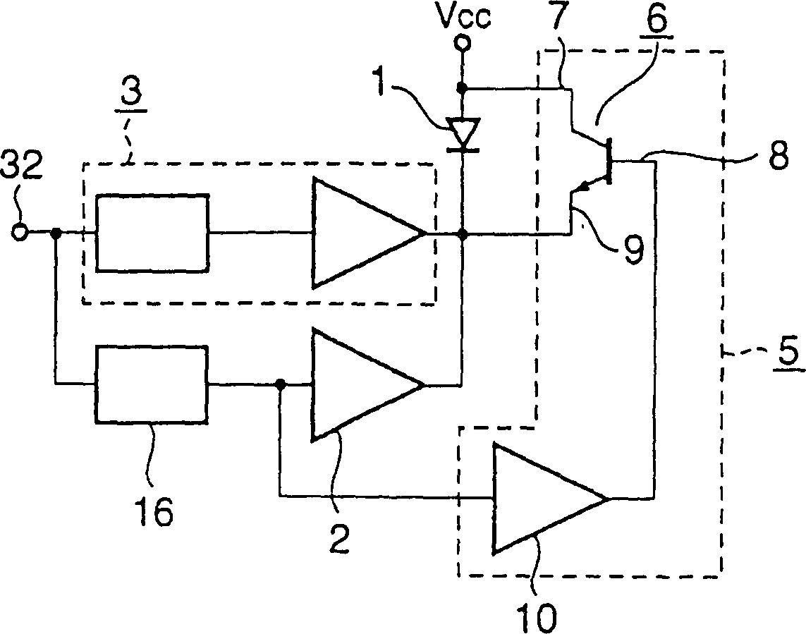
[0032] figure 1 A light emitting diode drive circuit according to the first embodiment of the present invention is shown. Such as figure 1 As shown, the input terminals of the pulse current generating circuit 3 and the pulse shaping circuit 16 are connected to the input terminal 32, and the input terminals of the first current switch circuit 2 and the discharge circuit 5 are connected to the output terminal of the pulse shaping circuit 16. The anode and cathode of LED1 are connected to the output end of the discharge circuit 5, and the output ends of the pulse current generating circuit 3 and the first current switch circuit 2 are connected to the cathode of the LED1. In this way, the first current switch circuit 2 is connected in series to the LED1, the discharge circuit 5 is connected in parallel to the LED1, and the pulse current generating circuit ...


PUM


Abstract

A light-emitting diode driving circuit according to an embodiment of this invention includes a light-emitting diode (1), a first current switch circuit (2) connected in series with the light-emitting diode (1), the first current switch circuit (2) turning on / off a current in accordance with an external input signal input from an input terminal (32), a pulse current generating circuit (3) connected in parallel with the first current switch circuit (2), the pulse current generating circuit (3) supplying a pulse current including a pulse width smaller than the pulse width of the external input signal and shaping a leading edge portion of an optical waveform output from the light-emitting diode (1) into a desired optical waveform, and a discharge circuit (5) connected in parallel with the light-emitting diode (1), the discharge circuit (5) quickly discharging charge stored in the light-emitting diode (1) when the current to the first current switch circuit (2) is turned off.

Description

technical field [0001] The present invention relates to a light-emitting diode (LED) drive circuit and an optical transmission module using it, in particular to its use in a high-speed optical transmission module or an optical transceiver. Background technique [0002] The existing light-emitting diode (LED) drive circuit for increasing the speed of the light output waveform, as disclosed in Japanese Patent Publication 7-74788 "High-Speed ​​Optical Transmission Circuit" published in 2017, has a speed-up circuit using the trailing edge time , to further peak the front part. [0003] Image 6 Shows a light emitting diode drive circuit according to the prior art. Such as Image 6 As shown, the input terminals of the first current switch circuit 33 , the buffer amplifier 34 and the inverter circuit 35 are connected to the input terminal 32 . The first capacitor 36 is connected to the output terminal of the buffer amplifier 34 , and the second current switch circuit 38 is conne...

Claims


Application Information

Patent Timeline
Patent Type & Authority Patents(China)
IPC IPC(8): H01L33/00H04B10/25H04B10/2507H04B10/40H04B10/50H04B10/58H04B10/60
CPCH04B10/508H04B10/502H04B10/50H04B10/40H04B10/00
Inventor 佐仓成之上西克二
Owner KK TOSHIBA
Why Eureka
Try Eureka