Floor plate steel truss structure

A steel truss and floor slab technology, applied in the field of floor slab steel truss structures, can solve problems such as unreasonable truss structures, damage to the bearing strength of floor slabs, and easy de-soldering, so as to achieve difficult de-soldering, high load-bearing capacity, and enhanced overall strength Effect

Inactive Publication Date: 2013-05-08
南方锐博新型建材有限公司
View PDF5 Cites 8 Cited by
  • Summary
  • Abstract
  • Description
  • Claims
  • Application Information

AI Technical Summary

Problems solved by technology

[0002] The truss structure in the steel truss floor slab in the prior art is unreasonable, which leads to easy de-soldering betwe

Method used


Image

  • Floor plate steel truss structure
  • Floor plate steel truss structure

Examples


Embodiment

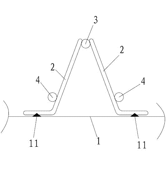
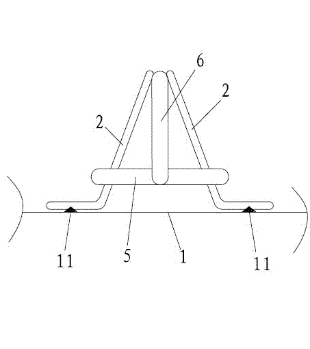
[0015] Embodiment: A kind of floor plate steel truss structure, such as Figure 1-2 As shown, bottom mold 1 is included, and bottom mold 1 has the welding bar 11 that cross section is triangular, and generally the spacing between two welding bars 11 of every pair of welding bars 11 is 10-15cm, and the present embodiment is 12cm; The bottom of reinforcement bar 2 is welded on corresponding welding bar 11, and upper chord reinforcement 3 is all welded between the upper end of every pair of web reinforcement 2, and the bottom of each web reinforcement 2 is welded with lower chord reinforcement 4; The length direction of upper chord reinforcement 3 and The length direction of the web bars 2 is in the same direction; the horizontal bars 5 are fixedly connected between the two ends of each pair of lower chord bars 4 on the same side; the horizontal bars 5 are perpendicular to the lower chord bars 4; the horizontal bars 5 are fixedly connected to the upper chord bars 3 There are vert...


PUM


Abstract

The invention relates to the building technology, in particular to a floor plate steel truss structure. The floor plate steel truss structure comprises a bottom die, web member steel bars fixedly connected with the bottom die, upper chord steel bars fixed on the web member steel bars and lower chord steel bars fixed on the web member steel bars, wherein the upper chord steel bars are arranged between upper ends of a pair of web member steel bars, and the length direction of the upper chord steel bars is in the same direction with the length direction of the web member steel bars, the lower chord steel bars are respectively arranged on lower portions of the corresponding web member steel bars, and horizontal ribs are fixedly connected between two end portions of the same side of each pair of the lower chord steel bars. The floor plate steel truss structure is high in connection strength, a loose weld phenomenon is not prone to occurring in the pouring process, and consequently the floor plates have high bearing capacity.

Description

technical field [0001] The invention relates to building technology, in particular to a floor plate steel truss structure. Background technique [0002] The truss structure in the steel truss floor slab in the prior art is unreasonable, which leads to easy de-soldering between the web reinforcement and the bottom form during the pouring process, thus destroying the bearing strength of the floor slab. Contents of the invention [0003] The object of the present invention is to provide a steel truss structure for floor slabs. The steel truss structure has high connection strength and is not prone to de-soldering during pouring, so that the floor slab has a higher bearing capacity. [0004] The above-mentioned technical purpose of the present invention is achieved by the following technical solutions: a floor slab steel truss structure, including a base form, a web reinforcement fixedly connected to the base form, and an upper chord reinforcement fixed to the web reinforcemen...

Claims


Application Information

Patent Timeline
IPC IPC(8): E04B5/38
Inventor 陈永德刘继国陈丽琴
Owner 南方锐博新型建材有限公司
Why Eureka
Try Eureka