Differential type pilot overflow valve

A pilot overflow valve and differential technology, applied in the field of hydraulic components, can solve the problems of short life, easy damage, easy vibration and howling, etc., and achieve the effect of reducing manufacturing requirements and reducing impact

Active Publication Date: 2013-05-08
GUANGXI LIUGONG MASCH CO LTD
View PDF7 Cites 8 Cited by
  • Summary
  • Abstract
  • Description
  • Claims
  • Application Information

AI Technical Summary

Problems solved by technology

[0003] The purpose of the present invention is to provide a main valve opening device with good stability, low noise and long service life for the shortcomings of the existing main valve opening device of the overflow valve, which is easily damaged due to large impact, has a short life, and is prone to vibration and howling. differential pilot relief valve

Method used


Image

  • Differential type pilot overflow valve
  • Differential type pilot overflow valve
  • Differential type pilot overflow valve

Examples


Embodiment 1

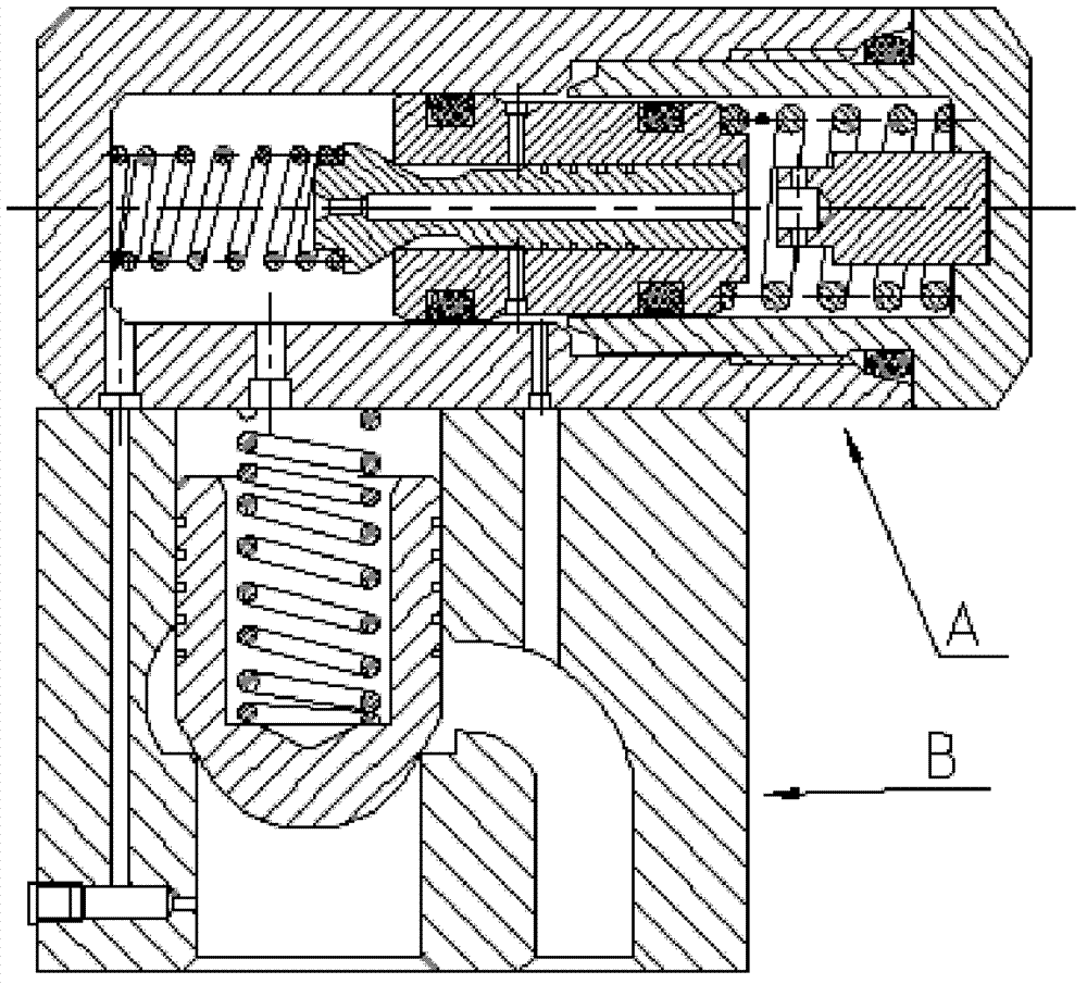
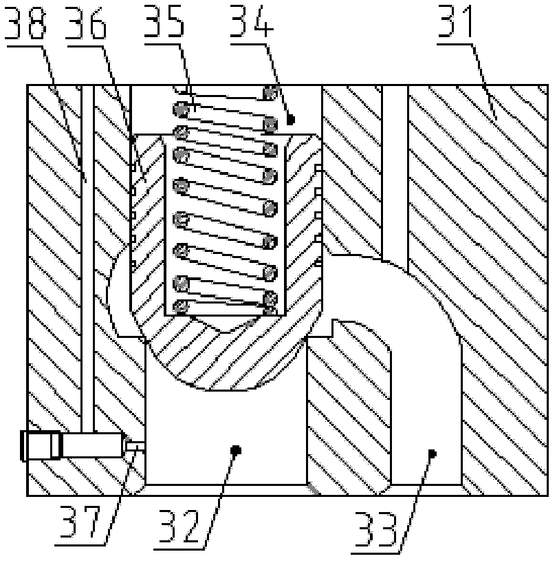
[0029] Such as figure 2 As shown, the main valve B of the differential pilot relief valve and the main valve opening device A fixedly connected with the main valve B. Such as image 3 As shown, the main valve includes a main valve body 31, and the main valve body 31 is provided with a main spool cavity and an oil spill port 33; a main spool 36 that can move axially is arranged in the main spool cavity, and the main spool One side of 36 is the main valve oil inlet 32, and the other side is the upper chamber 34, and the upper chamber 34 is provided with a return spring 35, one end of the return spring withstands the valve body 1 of the main valve opening device, and the other end withstands the main valve The core 36 pushes the main valve core 36 to the main valve oil inlet 32, and the main valve core 36 can move away from the direction of the main valve oil inlet to connect the main valve oil inlet 32 ​​with the oil overflow port 33.

[0030] Such as Figure 4 , Figure 5 ...

Embodiment 2

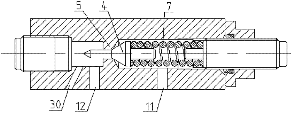
[0033] Such as Figure 7 As shown, compared with Embodiment 1, the difference of the differential pilot relief valve in this embodiment is that the main valve orifice 37 is set on the main valve core 36, and the main valve orifice 37 connects the upper cavity 34 communicates with the main valve oil inlet 32, because the upper chamber 34 communicates with the first chamber 3, so the first chamber 3 is directly connected to the main valve oil inlet through the upper chamber 34 through the main valve orifice 37 connected.

Embodiment 3

[0035] Such as Figure 8 As shown, compared with Embodiment 2, the difference of the differential pilot relief valve in this embodiment is that a sealing sleeve 29 is provided on the outside of the small diameter section of the pilot valve seat 5, and the inner wall of the sealing sleeve 29 Slidingly fit with the outer wall of the small-diameter section of the pilot valve seat 5 , the two ends of the sealing sleeve 29 are in contact with the valve body 1 and the bonnet 9 respectively, and are axially positioned by being squeezed by the bonnet 9 . In this embodiment, by providing the sealing sleeve 29, the coaxiality requirement between the sealing sleeve 29 and the pilot valve seat 5 can be easily met during the manufacturing process, which can reduce the difficulty of manufacturing. Another difference is that the limiting post 8 is integrated with the bonnet 9, which can also simplify the structure and reduce manufacturing difficulty and cost.


PUM


Abstract

The invention discloses a differential type pilot overflow valve to overcome the defects that impact between a pilot valve core and a pilot valve seat in the conventional pilot overflow valve is large, and the conventional pilot overflow valve is easy to damage, short in service life and large in noise. According to the pilot overflow valve, a differential pilot valve is arranged in a pilot valve cavity; the inner side of the pilot valve is provided with a first accommodation cavity which is communicated with an oil inlet, and the outer side of the pilot valve is provided with a second accommodation cavity communicated with the first accommodation cavity through a throttling hole; the pilot valve core is arranged in the pilot valve seat, and a sealing cone of the pilot valve core is positioned in the first accommodation cavity and is connected with a first buffer spring; the side of the second accommodation cavity is provided with a pressure regulating spring connected with the pilot valve seat; and a pilot valve gap, a radial through hole and an oil outlet between the pilot valve seat and the pilot valve core form a pilot valve opening leakage oil channel. By the damping effect of the differential pilot valve, the inverse pilot valve core, the buffer spring, the axial movable pilot valve, the pilot valve core and the pilot valve gap, the impact force generated when the pilot valve is opened can be reduced, and the pilot valve core is always in the stable state, so that the overflow valve has the advantages of small impact, long service life, stability and low noise.

Description

technical field [0001] The invention relates to a hydraulic component of a hydraulic system, in particular to a differential pilot overflow valve in the hydraulic system. technical background [0002] The existing split relief valve includes a main valve and a main valve opening device, the main valve opening device is used to control the hydraulic pressure in the upper chamber of the main valve, and the main valve core is opened by reducing the hydraulic pressure in the upper chamber. The existing main valve opening device is usually a pilot hydraulic valve, such as figure 1 As shown, the pilot valve seat 5 is fixed, and the pilot valve core 4 is positioned in the valve hole of the pilot valve seat 5 through the columnar positioning pin on its top and is intermittently matched with the valve hole. The pilot valve oil inlet 12 connected to the upper chamber has the second oil inlet 30 connected to the main valve oil inlet through the main valve orifice, and the pilot valve ...

Claims


Application Information

Patent Timeline
Patent Type & Authority Applications(China)
IPC IPC(8): F15B13/02
Inventor 高英达唐云娟
Owner GUANGXI LIUGONG MASCH CO LTD
Why Eureka
Try Eureka