Humidifier and humidification heater with the same

A technology for humidifiers and heaters, which can be used in air humidification systems, lighting and heating equipment, space heating and ventilation, etc., and can solve user discomfort, lowering, humidifier air supply path or condensation in the storage part of electrical components, etc. problems, to achieve the effect of suppressing condensation

Active Publication Date: 2013-05-08
PANASONIC CORP
View PDF6 Cites 5 Cited by
  • Summary
  • Abstract
  • Description
  • Claims
  • Application Information

AI Technical Summary

Problems solved by technology

[0003] However, when the room temperature is very low or the room temperature drops rapidly, there is a problem that condensation occurs on the air supply path inside the humidifier or the electrical component storage part due to the temperature difference between the inside of the humidifier and the room temperature.
[0006] However, in the above-mentioned existing structure, when the anti-condensation measures are implemented, there is a possibility that the user may feel uncomfortable due to changes in the air supply volume or warm air temperature that are not intended by the user, or may cause misunderstanding. When we think that it is abnormality of humidifier
Moreover, in order to take anti-condensation measures, it is necessary to have a room temperature detection member and a humidity detection member, and there are concerns about cost increase and reduction in productivity, and there is room for improvement in terms of ease of use and production cost.

Method used


Image

  • Humidifier and humidification heater with the same
  • Humidifier and humidification heater with the same
  • Humidifier and humidification heater with the same

Examples


Embodiment approach 1

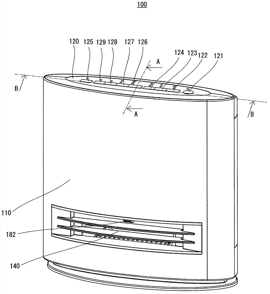
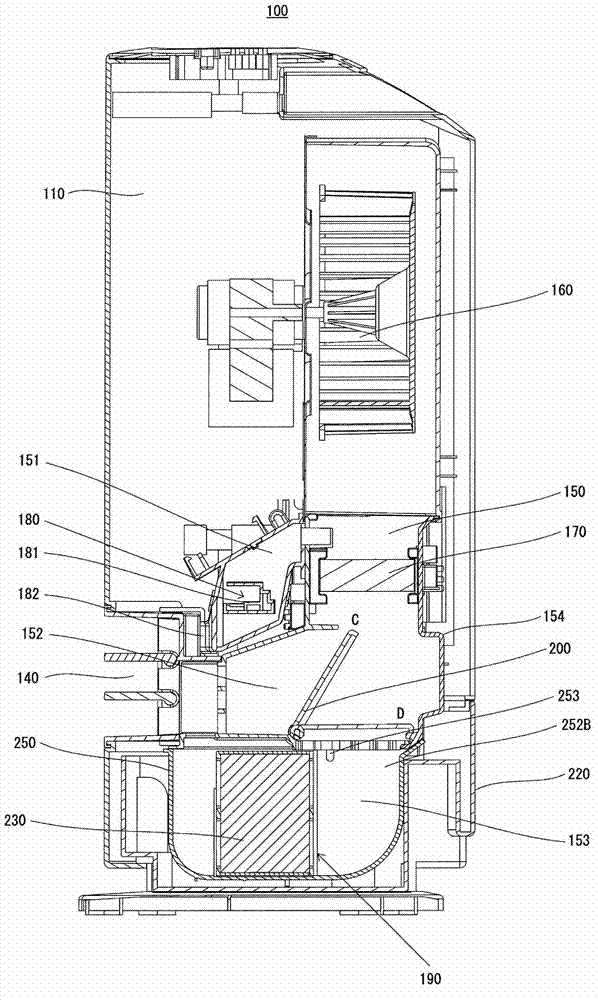
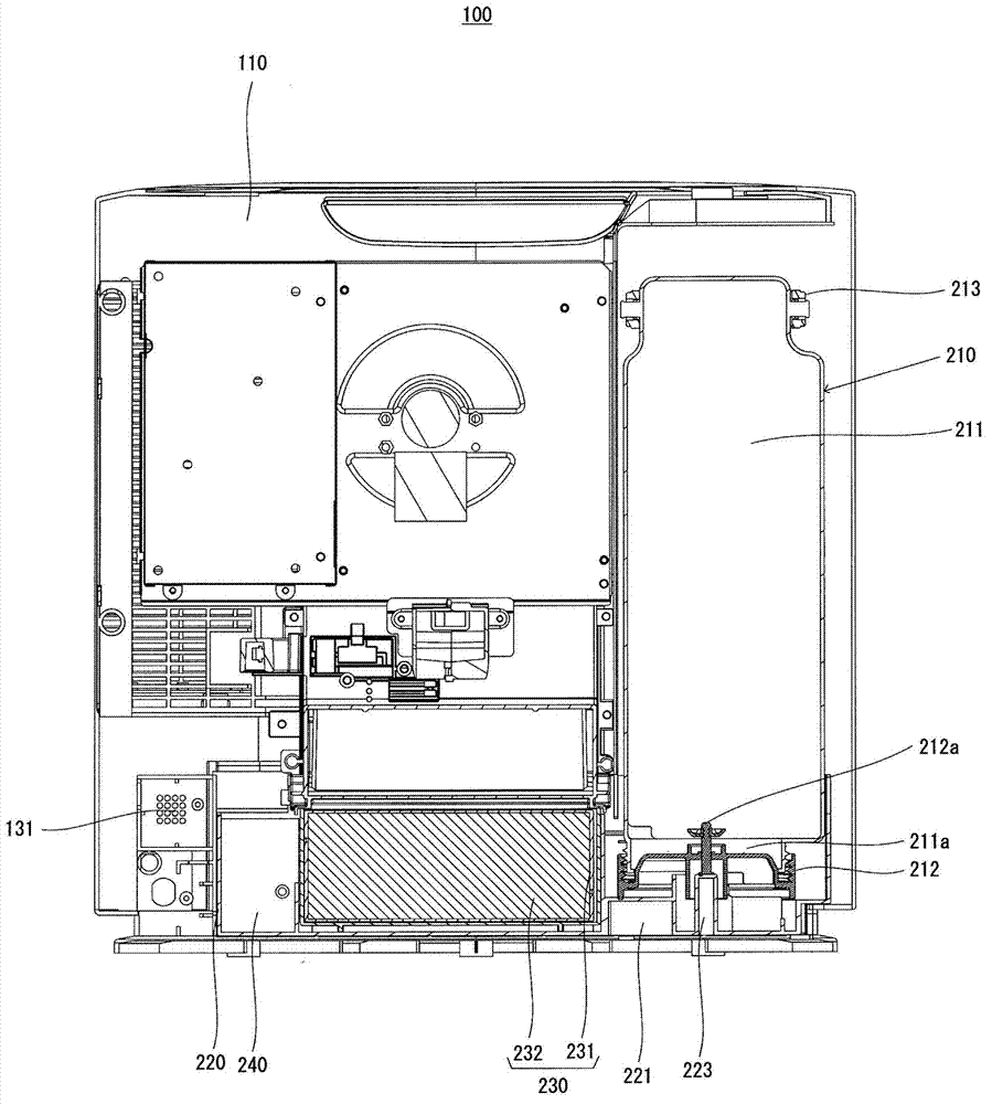
[0053] figure 1 It is a perspective view showing the appearance of the humidification heater according to Embodiment 1, figure 2 is alongfigure 1 A cross-sectional view of line AA is shown, image 3 is along figure 1 A cross-sectional view of line BB is shown, Figure 4 yes means figure 1 The perspective view of the loading and unloading operation of the water storage container of the humidification heater shown, Figure 5 is from figure 1 A perspective view of the main body of the humidifying heater shown with the water supply container and water supply tank removed.

[0054] In addition, in this embodiment, with figure 1 In the illustrated humidifying heater, the front side with the air outlet is defined as the front, the rear side with the air inlet is defined as the rear, the right side from the front surface toward the rear is defined as the right side, and the left side is defined as the left side. In addition, the detachable components will be described accordin...


PUM


Abstract

The present invention provides a humidifier and a humidification heater with the same, which can prevent dewing on the humidifier body. The heater is provided with the following components: an air path (150) which communicates an opening with an air inlet (130) and an air outlet (140) of the external surface of the humidifier body (110); a blower fan (160) which is configured at the middle part of the air path; a heater (170) which is configured at downstream part of the blower fan of the air path; a humidification filter (230) which is configured downstream part of the heater of the air path; and a filter tank (250) of which the inner space forms one part of the air path. The humidification filter is configured in the inner space of the filter tank. The filter tank is fixed at a preset position of a humidification tank (220). The humidifier body is provided with a tank accommodating part (112a) for accommodating the humidification tank. The wall part of the filter tank is provided with a ventilation port (253) which communicates the air path at upstream part of the humidification filter with the space formed by the tank accommodating part.

Description

technical field [0001] The present invention relates to a structure of a vaporization type humidifier that sends air to a humidification filter after absorbing water to vaporize, and a humidification heater including the humidifier. Background technique [0002] A humidifier is a device for adjusting indoor humidity, and there are various types such as a steam fan type, a steam type, an ultrasonic type, and a vaporization type. In the humidifier of the vaporization type, water is drawn from the water storage tank through the humidification filter, and air is circulated through the humidification filter to diffuse moisture contained in the humidification filter into the air to perform humidification. [0003] However, when the room temperature is very low or the room temperature drops rapidly, there is a problem that dew condensation occurs on the air supply path inside the humidifier or the electric component storage part due to the temperature difference between the inside ...

Claims


Application Information

Patent Timeline
Patent Type & Authority Applications(China)
IPC IPC(8): F24F6/00
Inventor 有川富夫鹤见直树
Owner PANASONIC CORP
Why Eureka
Try Eureka