
Method for calibrating transfer function in monitoring device

A transfer function and monitoring device technology, applied in the field of calibration, can solve the problems of low parameter accuracy of the transfer function, unsuitable calibration method, limited application of the calibration method, etc.

Active Publication Date: 2016-07-06
HISENSE BROADBAND MULTIMEDIA TECH
View PDF5 Cites 0 Cited by
  • Summary
  • Abstract
  • Description
  • Claims
  • Application Information

AI Technical Summary

Problems solved by technology

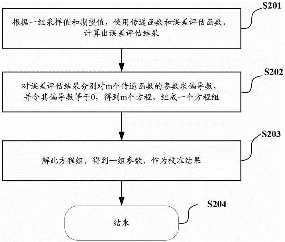
[0020] However, the inventors of the present invention have found that the calibration methods in the prior art are very limited in application occasions. For example, in the case of using a nonlinear transfer function or a nonlinear error evaluation function, the error evaluation result is a very complicated function, and its partial The system of equations composed of derivatives is very difficult to solve; therefore, the calibration methods of the prior art can hardly be applied in these situations
For example, in applications such as optical power monitoring results in the field of optical communications, the minimum relative error is required, and the evaluation function of its preferred parameters is a relative error evaluation function composed of a logarithmic function and an additive function. If the calibration of the existing technology is used method, the equations composed of its partial derivatives are very difficult to solve; that is to say, the calibration method in the prior art is not suitable for optical power monitoring occasions in the field of optical communication that require relatively small errors
[0021] In addition, in the process of solving the equation, the number of sampled values ​​and expected values ​​used as known values ​​corresponds to the number of parameters of the transfer function, usually equal to or several more than the number of parameters; as we all know, the used If the known values ​​are limited, the accuracy of the calculation results usually obtained is also limited
[0022] Therefore, in summary, the application occasions of the calibration method in the prior art are very limited, and the accuracy of the parameters of the calibrated transfer function is not high.

Method used


Image

  • Method for calibrating transfer function in monitoring device
  • Method for calibrating transfer function in monitoring device
  • Method for calibrating transfer function in monitoring device

Examples


Embodiment Construction

[0120] In order to make the object, technical solution and advantages of the present invention clearer, the present invention will be described in further detail below with reference to the accompanying drawings and preferred embodiments. However, it should be noted that many of the details listed in the specification are only for readers to have a thorough understanding of one or more aspects of the present invention, and these aspects of the present invention can be implemented even without these specific details.

[0121] As used herein, terms such as "module" and "system" are intended to include computer-related entities such as, but not limited to, hardware, firmware, a combination of hardware and software, software, or software in execution. For example, a module may be, but is not limited to being limited to being, a process running on a processor, a processor, an object, an executable, a thread of execution, a program, and / or a computer. For example, both an applicatio...


PUM


Abstract

The invention discloses a calibration device and a method for carrying out calibration on a transfer function in a monitoring device. The method comprises the steps: setting m parameters of the transfer function as parameter values of first iteration; carrying out at least one iterative process; in a jth iterative process, if a calculated error evaluation value s is smaller than an evaluation target value according to AD1-ADn, Rxp1-Rxpn, and a parameter value of jth iteration, confirming the parameter value of the jth iteration as a calibration result; if not, adjusting the parameter value of the jth iteration according to a shrinkage algorithm, obtaining a parameter value of j+1th iteration, and continuing the next iterative process, wherein the Rxp1-Rxpn are n index values of a monitored object, and the AD1-ADn are n sampling values. Due to the fact that the shrinkage algorithm is adopted to carry out iterative calculation on the parameters of the transfer function, the process of missing solution of equations is avoided, the method can be applied to situations of a non-linear transfer function and a non-least-square error evaluation function, and accordingly the calibration method has wide application situations.

Description

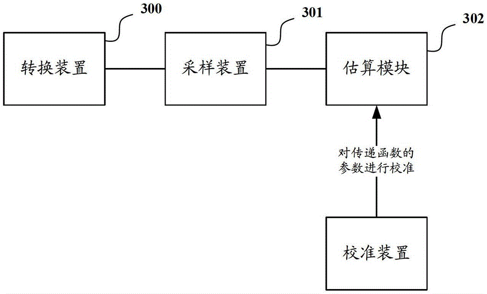
technical field [0001] The invention relates to a calibration technology, in particular to a calibration device and a method for calibrating a transfer function in a monitoring device. Background technique [0002] In the field of engineering, for example, in the field of measurement, control, and communication, it is often necessary to monitor certain physical quantities; the monitoring process of the monitoring device is usually as follows figure 1 As shown: the sampling value collected by the sampling device is input into the estimation device, and the estimation device estimates the input sampling value through a preset transfer function, and the obtained estimated value is used as the value of the monitored object. The sampling device can usually include an AD (analog-to-digital) converter; the estimation device can usually be a single-chip microcomputer, or a microprocessor, or a CPU and other devices. [0003] Before the estimation device is applied to the monitoring...

Claims


Application Information

Patent Timeline
Patent Type & Authority Patents(China)
IPC IPC(8): G06F17/15
Inventor 林青合张华
Owner HISENSE BROADBAND MULTIMEDIA TECH
Learn More