Screening can and telephone receiver thereof
A shielding shell and receiver technology, applied in the fields of magnetic field/electric field shielding, earpiece/headphone accessories, electrical components, etc., can solve the problems of simple and single structure of the receiver, single sound wave, etc., and achieve rich output, suppress high-frequency output, and have a simple and reasonable structure. Effect
- Summary
- Abstract
- Description
- Claims
- Application Information
AI Technical Summary
Problems solved by technology
Method used
Image
Examples
Embodiment 1
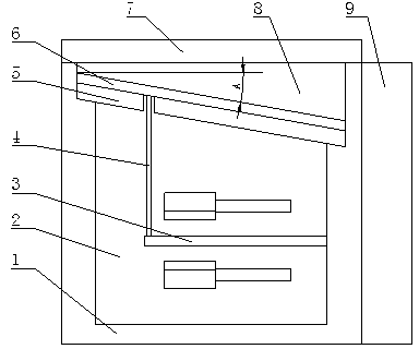
[0031] like figure 1 As shown, as a first preferred embodiment, a shielding shell includes a bottom box 1 and a box cover 7, the box cover 7 is arranged on the top of the bottom box 1, and the inside of the bottom box 1 is provided with steps, the The bottom box 1 is divided into a front chamber 8 of the bottom box and a rear chamber 2 of the bottom box by the step. The slope of the step forms an angle A with the horizontal plane, and the angle A is 15°.
[0032] A shielded case receiver includes a shielded case, a circuit board 9 and a sound transmission mechanism, the circuit board 9 is arranged on the outer wall of the bottom box 1 , and the sound transmission mechanism is arranged inside the bottom box 1 .
[0033] The sound transmission mechanism includes a diaphragm 6, a diaphragm frame 5, a vibration conducting rod 4 and a vibration device 3, the diaphragm frame 5 is bonded to the step, and the vibration device 3 is arranged behind the bottom box In the cavity 2, the v...
Embodiment 2
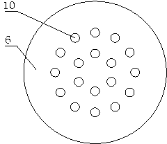
[0036] like figure 2 As shown, as the second preferred embodiment, the rest is the same as Embodiment 1, except that 18 through holes 10 are evenly opened on the diaphragm 6, and the through holes 10 are circular.
[0037] In the above-mentioned embodiment 2, the diaphragm 6 is provided with a through hole 10, which can reduce the weight of the diaphragm 6 of the receiver, enhance the high-frequency output of the receiver, and increase the response bandwidth of the receiver.
Embodiment 3
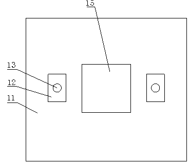
[0039] like image 3 As shown, as the third preferred embodiment, the rest is the same as embodiment 1 or 2, the difference is that the circuit board 9 includes a circuit board main body 11, and terminals 12 are respectively provided at both ends of one side of the circuit board main body 11, Solder spots 13 are provided on the terminals 12 , and an opening and closing hole 15 is opened in the middle of the circuit board main body 11 , and the opening and closing hole 15 is circular.
[0040] In the above-mentioned embodiment 3, the circuit board body 11 is provided with opening and closing holes 15, which has a simple and reasonable structure, can enhance low-frequency output, enrich sound output, is more convenient, and meets the needs of people's daily life.
PUM
 Abstract
Description
Claims
Application Information
 - R&D
- Intellectual Property
- Life Sciences
- Materials
- Tech Scout
- Unparalleled Data Quality
- Higher Quality Content
- 60% Fewer Hallucinations
Browse by: Latest US Patents, China's latest patents, Technical Efficacy Thesaurus, Application Domain, Technology Topic, Popular Technical Reports.
© 2025 PatSnap. All rights reserved.Legal|Privacy policy|Modern Slavery Act Transparency Statement|Sitemap|About US| Contact US: help@patsnap.com


