Unlock instant, AI-driven research and patent intelligence for your innovation.
Roadway image rendering device and roadway image rendering method
What is Al technical title?
Al technical title is built by PatSnap Al team. It summarizes the technical point description of the patent document.
A technology for depicting devices and roads, which is applied in the processing of instruments, maps/plans/charts, 3D images, etc., and can solve problems such as no public road node matching method
Inactive Publication Date: 2013-05-08
MITSUBISHI ELECTRIC CORP
View PDF5 Cites 1 Cited by
Summary
Abstract
Description
Claims
Application Information
AI Technical Summary
This helps you quickly interpret patents by identifying the three key elements:
Problems solved by technology
Method used
Benefits of technology
Problems solved by technology
[0006] In addition, in the map information creation method disclosed in Patent Document 1, easily recognizable map information can be created in which roads have natural gradients, but a method for matching road nodes is not disclosed. The boundary part of the road cannot be displayed with a clear connection relationship
Method used
Image
Click on the blue label to locate the original text in one second.
Reading with bidirectional positioning of images and text.
Examples
Embodiment approach 1
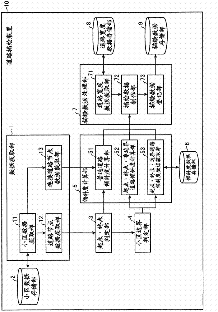
[0026] figure 1 It is a block diagram showing the configuration of the road drawing device according to Embodiment 1 of the present invention.
[0027] The road drawing device 10 includes: a data acquisition unit 1, a cell data storage unit 2, a start / end point determination unit 3, a cell boundary determination unit 4, an inclination calculation unit 5, an inclination data storage unit 6, a rendering data processing unit 7, a road Width data storage unit 8 and rendering data storage unit 9 .
[0028] The data acquisition unit 1 includes: a celldata acquisition unit 11 , a road node data acquisition unit 12 and a connected road node data acquisition unit 13 . The cell data acquisition unit 11 acquires predetermined cell data from the cell data storage unit 2 storing the cell data. The road node data acquisition unit 12 acquires data related to predetermined road nodes from cell data. The connected road node data acquisition unit 13 acquires data related to road nodes conn...
Embodiment approach 2
[0087] In the first embodiment described above, a configuration was shown in which drawing data was created using the inclination data stored in advance in the inclination data storage unit 6. However, in this second embodiment, a configuration is shown in which the stored Based on the inclination data, the inclination of road nodes is calculated using a pre-unified calculation method, and drawing data is created.
[0088] Figure 7 It is a block diagram showing the configuration of the road drawing device according to Embodiment 2 of the present invention. In this second embodiment, the coordinate transformation unit 21 is newly added to the road drawing device 10 shown in the first embodiment, and the start point and end point are newly added in the start point, end point, and boundary road gradient data acquisition unit 53. - Boundary road inclination calculation unit 54 . In addition, a different gradient calculation method from Embodiment 1 is used in the start point, e...
PUM
Abstract
The present invention comprises: a roadway node data acquisition unit, which acquires node data that denotes a node that corresponds to a prescribed location on a roadway from one parcel's worth of image rendering data; a normal roadway incline computation unit, which computes the inclination of a node when it is determined by a start point-end point determination unit that the node is not positioned at the start point or the end point of the roadway; a start point-end point non-boundary roadway incline computation unit, which computes the inclination of a node when it is determined that the node is positioned at either the start point or the end point of the roadway, and when it is determined by a parcel boundary determination unit that the node is not positioned at the boundary of a parcel; a start point-end point boundary roadway incline data acquisition unit, which acquires previously computed incline data when it is determined that a node is positioned at the boundary of a parcel: and an image rendering data processing unit, which creates image rendering data from either the computed degree of incline or the acquired incline data, and previously stored roadway width data, and stores said image rendering data.
Description
technical field [0001] The present invention relates to a road drawing device and method for creating map information for three-dimensional display. Background technique [0002] use Figure 13 A conventional road drawing method for three-dimensional display will be described. exist Figure 13 In (a), each road node O, P, Q and the connection road (road link) connecting them are shown. In addition, each road node is managed in an area called a parcel, and the road nodes O and P are managed in the parcel R, and the road nodes P and Q are managed in the parcel S. exist Figure 13 In (b), each road node O, P, Q is allocated with a specified width, and two width allocation nodes O', O'', P', P'', Q', Q'' are newly created . Next, if Figure 13 As shown in (c), generate a polygon that connects the newly created width allocation nodes O', O'', P', P'', Q', Q'', and finally as Figure 13 As shown in (d), roads are drawn at positions equivalent to polygons. In addition, the widt...
Claims
Application Information
Patent Timeline
Application Date:The date an application was filed.
Publication Date:The date a patent or application was officially published.
First Publication Date:The earliest publication date of a patent with the same application number.
Issue Date:Publication date of the patent grant document.
PCT Entry Date:The Entry date of PCT National Phase.
Estimated Expiry Date:The statutory expiry date of a patent right according to the Patent Law, and it is the longest term of protection that the patent right can achieve without the termination of the patent right due to other reasons(Term extension factor has been taken into account ).
Invalid Date:Actual expiry date is based on effective date or publication date of legal transaction data of invalid patent.

