
Reciprocating double moving cutter cutting test device

A test device, reciprocating technology, applied in the field of machinery, can solve the problems of complicated changing test parameters, inconvenient research, crop harvesting season restrictions, etc., and achieve the effect of reducing the probability of failure, simplifying the installation and debugging process, and compact structure.

Active Publication Date: 2013-05-15
NANJING AGRI MECHANIZATION INST MIN OF AGRI
View PDF5 Cites 25 Cited by
  • Summary
  • Abstract
  • Description
  • Claims
  • Application Information

AI Technical Summary

Problems solved by technology

However, the field test of the cutter is greatly affected by the field environment, it is more complicated to change the test parameters, it is more difficult to collect and process the signal, and the test error fluctuates greatly, which is very inconvenient for research, and the field test is limited by the crop harvest season
[0003] Traditional harvesters are usually single-moving knife harvesters, which have problems such as low cutting speed, large reciprocating inertial force, and large vibration. Therefore, it has become a demand to research and design a cutter that can solve the problems of traditional cutters.

Method used


Image

  • Reciprocating double moving cutter cutting test device
  • Reciprocating double moving cutter cutting test device
  • Reciprocating double moving cutter cutting test device

Examples


Embodiment Construction

[0022] The present invention will be further explained below in conjunction with the accompanying drawings and specific embodiments. It should be noted that the words "front", "rear", "left", "right", "upper" and "lower" used in the following description refer to the directions in the drawings, and the words "inner" and "outer ” refer to directions towards or away from the geometric center of a particular part, respectively.

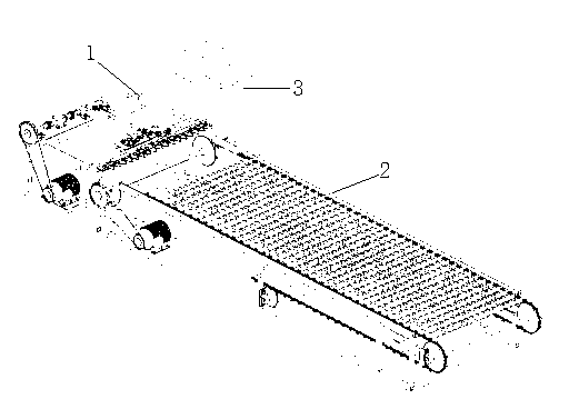
[0023] Overall structure of the present invention sees figure 1 , the cutting mechanism 1 is docked with the stalk feeding mechanism 2, the upper blade 116 and the lower blade 120 are located above the transmission wheel 203, and the stalk feeding mechanism 2 is fed to the cutting edge of the cutting mechanism 1 to be cut.

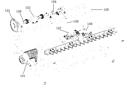
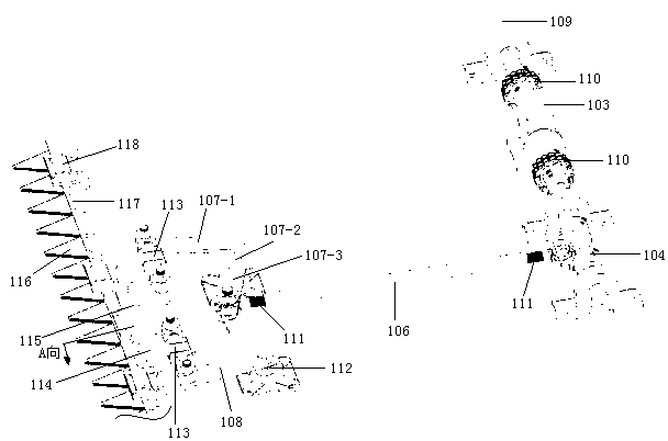
[0024] The concrete structure of cutting mechanism of the present invention sees figure 2 and image 3 , the motor 101 and the belt drive 102 are installed on the outside of the cutting frame 105, the motor 101 drives the connect...


PUM


Abstract

A reciprocating double moving cutter cutting test device comprises a cutting mechanism, a stalk feeding mechanism and a monitoring operation mechanism. Input power of a motor drives, through a connecting rod, an upper cutter rod and a lower cutter rod to move parallelly in different directions so that an upper blade and a lower blade which are adjacent move, are staggered and overlapped, and cut crops. A torsion rotating speed sensor is arranged on a power input shaft. A pull force sensor is arranged between the upper cutter rod and the lower cutter rod and a left rocker arm and a right rocker arm. A rotating speed sensor is arranged beside a transmission wheel. The torsion rotating speed sensor, the pull force sensor and the rotating speed sensor are used for inducting and recoding parameters in cutting processes. A best parameter combination is calculated through a computer. According to the reciprocating double moving cutter cutting test device, two layers of moving cutters simultaneously move in the different directions at the same speed, and inertia force of the upper cutter rod and the lower cutter rod is offset, so that a cutter is prevented from producing severe swings; and one connecting rod is used for transmitting power so that accuracy of motion of the upper blade and the lower blade is improved, and installation and debugging processes are reduced.

Description

technical field [0001] The invention relates to a crop cutter for testing, which is a cutting test device for simultaneously cutting crops with double-layer movable knives, and belongs to the field of machinery. Background technique [0002] The cutter is one of the core components of the harvester. The rationality of the cutter design directly affects the working performance of the harvester. Various parameters of the cutter require a lot of experiments to determine the optimal parameter value. The research is mainly to determine the best combination of cutting speed, feeding speed and blade geometry parameters through experiments and to study the interaction among them. However, the field test of the cutter is greatly affected by the field environment, it is more complicated to change the test parameters, it is more difficult to collect and process the signal, and the test error fluctuates greatly, which is very inconvenient for research, and the field test is limited by...

Claims


Application Information

Patent Timeline
Patent Type & Authority Applications(China)
IPC IPC(8): A01D34/13A01D34/30
Inventor 沈成陈巧敏李显旺王锦国张彬黄继承汪志兵
Owner NANJING AGRI MECHANIZATION INST MIN OF AGRI
Learn More