Supercharge Your Innovation With Domain-Expert AI Agents!

Turning clamping device

A technology of clamping mechanism and jaws, which is applied in the field of workpiece clamping devices, and can solve problems such as uneven placement of workpieces, unstable clamping, and looseness

Inactive Publication Date: 2013-05-15
CHONGQING JUKANG BUILDING MATERIAL
View PDF0 Cites 10 Cited by
  • Summary
  • Abstract
  • Description
  • Claims
  • Application Information

AI Technical Summary

Problems solved by technology

[0002] At present, in the process of workpiece processing, it is often necessary to fix the workpiece before subsequent processing, so the flip clamping device is widely used in the field of workpiece processing, and the disadvantages of the existing flip clamping device are: 1. The clamping is unstable and loose ; 2. The workpiece is not placed smoothly when clamping

Method used


Image

  • Turning clamping device

Examples


Embodiment Construction

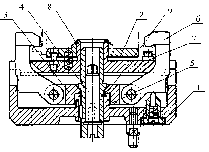
[0008] Such as figure 1 Described, a kind of overturning clamping device, comprises base 1, is provided with driving mechanism, clamping mechanism and limit mechanism on base 1, and driving mechanism comprises axle 4, axle sleeve 5, axle 4 and axle sleeve 5 are used for The countersunk head bolts are fixedly connected, and the shaft sleeve 5 is provided with a slope; the clamping mechanism includes a jaw 6, a floating top column 7, and a centering plate 2. One end of the jaw 6 is hinged to the bracket 3, and the bracket 3 is connected to the shaft sleeve. 5 inclined surface contact, the inclined surface of the bracket 3 cooperates with the sleeve provided on the shaft sleeve 5, the bracket 3 is driven by the shaft sleeve, the other end of the jaw 6 contacts the workpiece, and the workpiece can be clamped by swinging inward. 7 is set on the base 1, and the upper end is in contact with the workpiece; the centering disc 2 is also set on the base 1; the limit mechanism includes an...


PUM


Abstract

The invention relates to the field of workpiece clamping devices, in particular to a turning clamping device. The turning clamping device comprises a drive mechanism, a clamping mechanism, and a limiting mechanism. The drive mechanism comprises a shaft and a shaft sleeve which are fixedly connected through flush bolts. A slant is arranged on the shaft sleeve. The clamping mechanism comprises a clamping claw, a floating shore, and a centering disc. One end of the clamping claw is hinged with a support contacted with the slant of the shaft sleeve. The other end of the clamping claw is contacted with a workpiece and capable of clamping the workpiece by turning inward. The floating shore is arranged on the base seat. The upper end of the floating shore is arranged on the base seat. The centering disc is arranged on the base seat. The limiting mechanism comprises an upper split ring and a lower split ring. The upper split ring is arranged on the base seat. The lower slit ring is arranged on the shaft sleeve. The turning clamping device is capable of clamping the workpiece stably and leveling the workpiece at the same time.

Description

technical field [0001] The invention relates to the field of workpiece clamping devices, in particular to an overturning clamping device. Background technique [0002] At present, in the process of workpiece processing, it is often necessary to fix the workpiece before subsequent processing, so the flip clamping device is widely used in the field of workpiece processing, and the disadvantages of the existing flip clamping device are: 1. The clamping is unstable and loose ; 2. The workpiece is not placed smoothly when clamping. Contents of the invention [0003] The object of the present invention is to provide a flip clamping device that does not loosen the workpiece when clamping the workpiece and can adjust the workpiece stably. [0004] In order to achieve the above object, the technical solution of the present invention is: a flip clamping device, including a base, on which a driving mechanism, a clamping mechanism and a limit mechanism are arranged, and the driving m...

Claims


Application Information

Patent Timeline
IPC IPC(8): B23Q3/00
Inventor 周炫张信聪
Owner CHONGQING JUKANG BUILDING MATERIAL
Features
  • R&D
  • Intellectual Property
  • Life Sciences
  • Materials
  • Tech Scout
  • Unparalleled Data Quality
  • Higher Quality Content
  • 60% Fewer Hallucinations
Learn More