
Height adjustable novel building support

A new type of high-level technology, applied in the direction of construction, building structure, and on-site preparation of building components, can solve problems such as inconvenient loading and unloading, shortened service life, and increased wear of screw teeth, and achieves convenient adjustability, Improve work efficiency and avoid shaking effect

Inactive Publication Date: 2013-05-15
TIANJIN UNIV
View PDF10 Cites 7 Cited by
  • Summary
  • Abstract
  • Description
  • Claims
  • Application Information

AI Technical Summary

Problems solved by technology

The utility model discloses an adjustable building column, the scheme of which simply adopts the design structure of an adjusting nut and a screw rod. Although this structure solves the problem of the adjustable height of the support to a certain extent in theory, its disadvantages are: The disadvantages are: 1) The adjustable nut and the column with the screw rod need to have higher precision, which will increase the processing and maintenance costs of the bracket; 2) The adjustable nut is slow in large-scale adjustment or loading and unloading, which affects work efficiency ;3) Since the teeth of the screw rod are exposed to the outside, in the harsh environment of the construction site, the wear of the teeth of the screw rod will be aggravated and the service life will be shortened; 4) The column body and the screw rod are matched at intervals, which will cause shaking And moving, inconvenient during loading and unloading
However, there are the following problems in practical application: 1) If the adjustment design between the branch pipe and the casing is unreasonable, the adjustment will be more inconvenient when the pillar is required to be high, that is, the height adjustment range is limited by the adjustment groove; 2) The bushing and the branch pipe adopt a clearance fit, and can rotate relative to each other in the radial direction, so it is difficult to insert the positioning rod, which affects the work efficiency; 3) The bushing and the branch pipe are not axially fixed and constrained, so that the branch pipe shakes in the casing, Affect the quality of work construction

Method used


Image

  • Height adjustable novel building support
  • Height adjustable novel building support
  • Height adjustable novel building support

Examples


Embodiment Construction

[0030] Specific embodiments of the present invention will be described in detail below in conjunction with the accompanying drawings. If there are exemplary contents in these embodiments, they should not be construed as limiting the present invention.

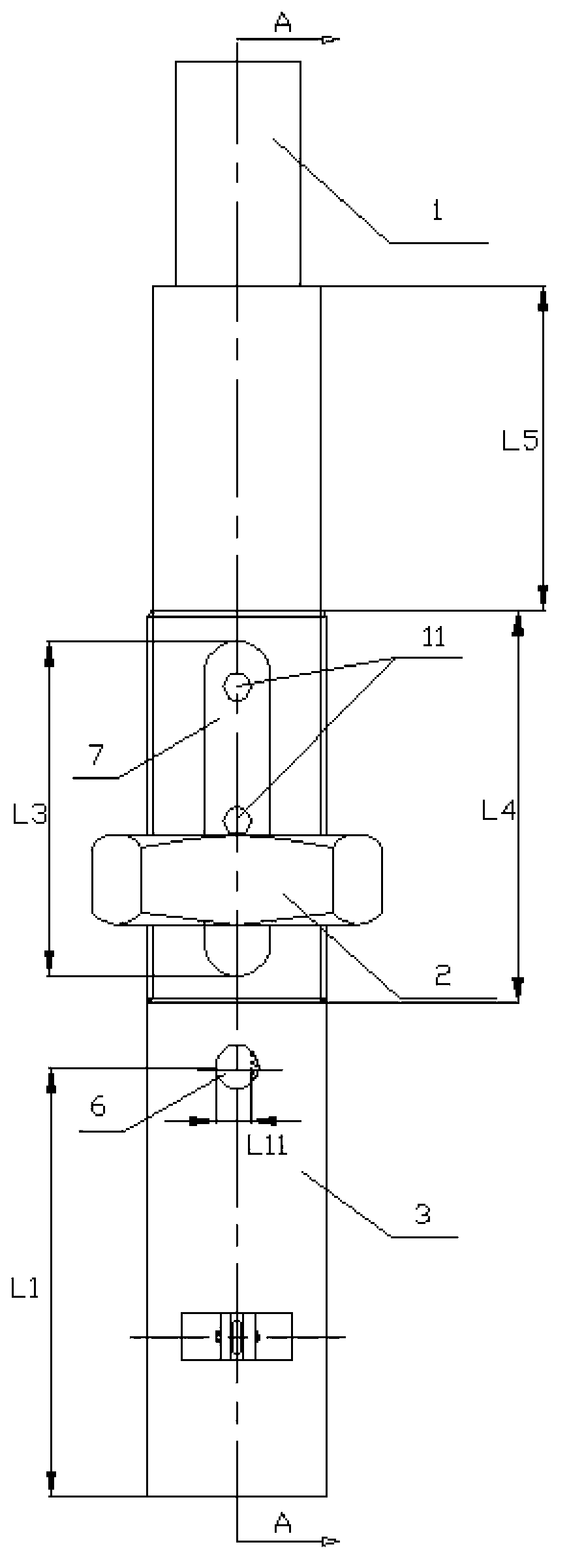
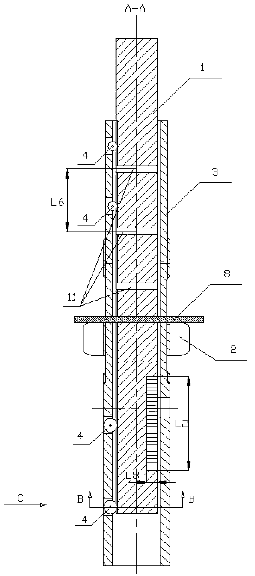
[0031] Such as Figure 1-9 As shown, the present invention includes an inner column 1, an adjusting nut 2, a sleeve 3, a roller 4, a roller shaft 5, a positioning pin 8 and an adjusting handle 9. The outer diameter of one end of the sleeve 3 is threaded, and the outer diameter of the threaded part of the sleeve 3 is smaller than or equal to the inner diameter of the thread of the adjusting nut 2, so as to facilitate the loading and unloading of the adjusting nut 2. The threaded part of the sleeve 3 is provided with a sleeve groove 7. The lower part of the threaded part of the sleeve 3 is provided with a lifting adjustment hole 6 (the lifting adjustment hole can also be set on the upper part of the thread. In this invention, onl...


PUM


Abstract

The invention discloses a height adjustable novel building support which comprises an inner column (1) and a sleeve (3). The inner column (1) is arranged in the sleeve (3), and does axial lifting movement with a rolling wheel (4) as supporting in the inner column (1). The inner column (1) drives the rolling wheel (4) to do radial rotation with a rolling wheel shaft (5) as a rotating center in a guide groove of the inner column (1). Compared with the prior art, the height adjustable novel building support has the advantages of being simple in structure, enabling adjustment of an upright column to be more convenient, facilitating scenic operation of workers, being capable of realizing large-distance adjustment and close-range fine adjustment types, improving work efficiency, carrying out axial positioning and radial positioning of the sleeve and the upright column, and avoiding inconvenience of construction due to shake and axial rotation in the using process.

Description

technical field [0001] The invention relates to building supports in the field of construction, in particular to a novel height-adjustable building support. Background technique [0002] In the process of building construction, no matter in the construction of buildings, workshops, roads, bridges, etc., building supports are inseparable. It is necessary to build some supports for pouring reinforced concrete or rubber at the construction site. Currently used The structural design of the building support is unreasonable, its length cannot be adjusted, it is inconvenient to use, and its safety performance is poor. The building supports currently used are mostly wooden supports and steel pipe supports. Wooden brackets are mainly sawn wooden beams as columns for upright support according to the specific height. If the height is lower than the actual height, bricks or wooden plugs are used for adjustment. It is easy to tilt or even fall over, and the height cannot be adjusted in...

Claims


Application Information

Patent Timeline
Patent Type & Authority Applications(China)
IPC IPC(8): E04G25/06
Inventor 徐传超李波徐庆国
Owner TIANJIN UNIV
Learn More