Throttle valve device

A technology of throttle and throttle valve, which is applied in engine control, machine/engine, mechanical equipment, etc. It can solve the problems of poor freezing release and increased contact area, so as to improve release, reduce freezing, and improve heat dissipation Effect

Inactive Publication Date: 2013-05-15
AISAN IND CO LTD
View PDF10 Cites 6 Cited by
  • Summary
  • Abstract
  • Description
  • Claims
  • Application Information

AI Technical Summary

Problems solved by technology

However, since the size of the length R1 is required in accordance with the shape of the ball bearing 83 on the downstream side of the hole 82, as Figure 18 As shown, the contact area S1 of the ice J1 generated between the throttle body 85 and the hole 82 and the inner wall of the hole 82 tends to increase.
Therefore, since the contact area S1 is relatively large, the throttle valve element 85 must be rotated with a large torque by a motor in order to release the freeze accordingly, and the release performance of the freeze is not good.

Method used


Image

  • Throttle valve device
  • Throttle valve device
  • Throttle valve device

Examples


no. 1 Embodiment approach

[0044] Hereinafter, a first embodiment embodying the throttle device of the present invention will be described in detail with reference to the drawings. The throttle device of the present embodiment is provided in an intake passage of an automobile engine, and is used to adjust the intake air amount of the engine.

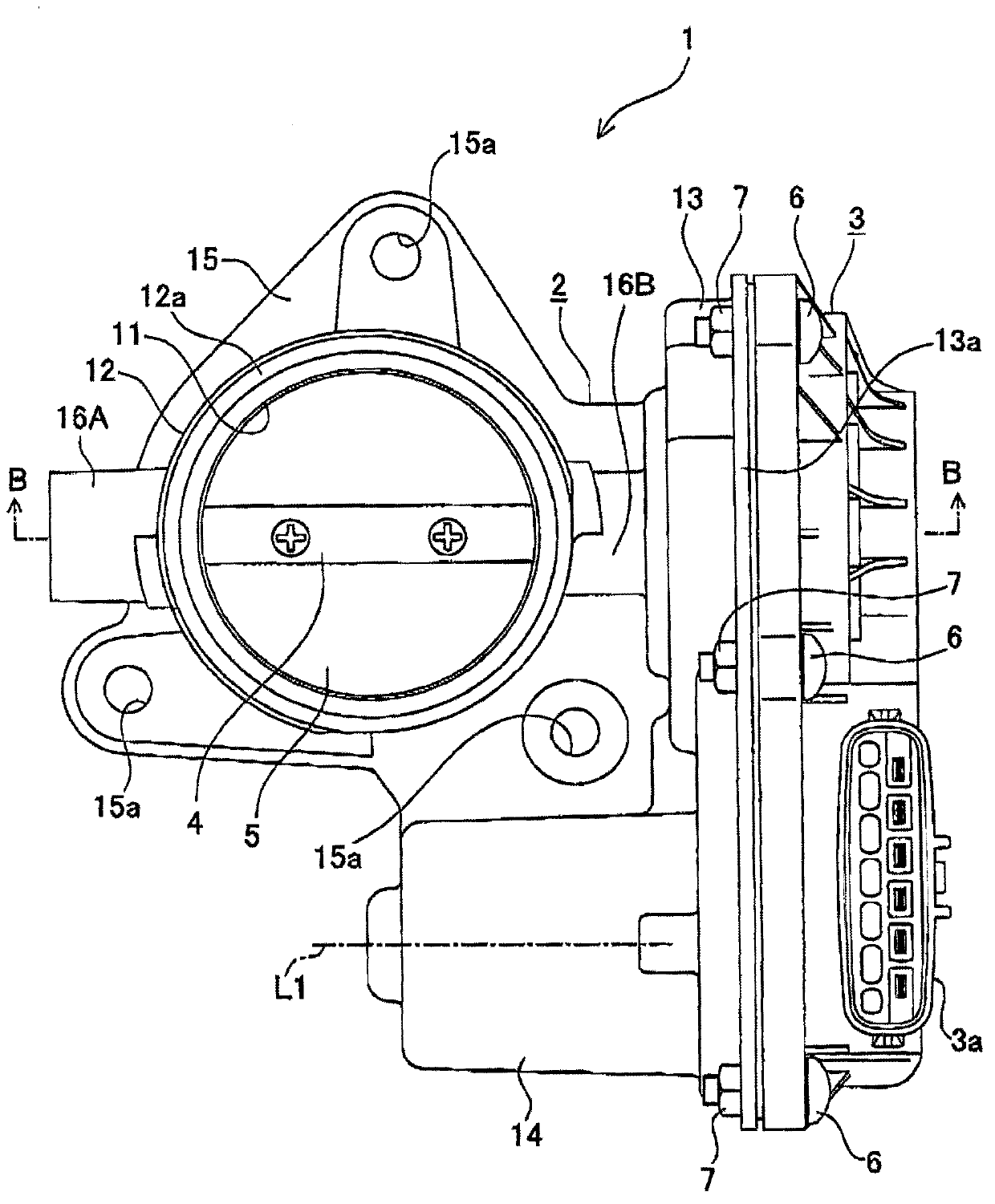
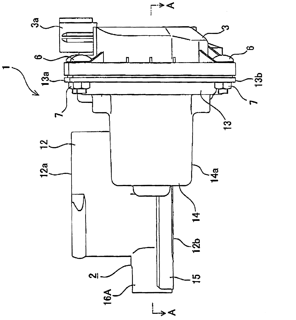
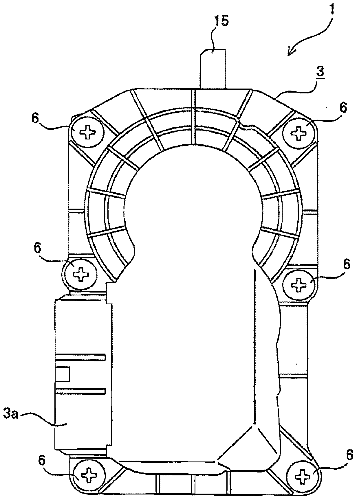
[0045] figure 1 The throttle device 1 according to the present embodiment is shown in a front view. figure 2 middle use figure 1 The bottom view of shows the throttle device 1. image 3 middle use figure 1 The right side view of shows the throttle device 1. like figure 1 , figure 2 As shown, the throttle device 1 includes a metal throttle body 2 and a resin gear cover 3 .

[0046] The throttle body 2 includes: a cylindrical throttle tube 12, which has a hole 11 communicating with the intake passage of the engine; a gear box 13, which accommodates the gear mechanism 9 inside (refer to Figure 4 ) etc.; motor casing 14, which accommodates the motor 8 i...

no. 2 Embodiment approach

[0074] Next, a second embodiment embodying the throttle device of the present invention will be described in detail with reference to the drawings.

[0075] In addition, in the following description, the same code|symbol is attached|subjected to the same component as 1st Embodiment, and description is abbreviate|omitted, and it demonstrates centering on the difference from 1st Embodiment.

[0076] The difference between the configuration of the present embodiment and the configuration of the first embodiment lies in the shape of the manifold 51 connected to the throttle tube 12 . Figure 15 A state in which the manifold 51 is connected to the throttle pipe 12 is schematically shown in a sectional view. That is, in this embodiment, if Figure 15 As shown, the intake passage 52 in the manifold 51 is formed such that the diameter gradually decreases from the one end 51 a of the manifold 51 toward the downstream side.

[0077] Therefore, since the intake passage 52 of the manifo...


PUM


Abstract

The invention provides a throttle valve device, which can improve removing performance of freezing between a valve core and a hole inner wall of a throttle valve. The throttle valve device is characterized in that, a throttle valve shaft (4) is made to rotate via use of a motor, etc. An opening degree, which is decided by a throttle valve core (5), of a hole (11) is changed, and air inlet flow of the hole is adjusted. The throttle valve shaft is supported to be rotatable by a pair of sliding bearings (21A, 21B) disposed corresponding to two end parts of the throttle valve shaft. Two bearings are disposed at a throttle valve body (2) or a throttle valve pipe (12) in a mode that the throttle valve shaft is adjacent to a downstream side end (11b) of the hole. When the throttle valve core becomes a closed state of almost completely closing the hole, the throttle valve core is configured to form a specified closed angle (theta 1) with the radial direction of the hole, one end part (5a) of the throttle valve is adjacent to a downstream side end of the hole. When the throttle valve core starts to open the hole, one end part (5a) of the throttle valve is immediately exposed.

Description

technical field [0001] The invention relates to a throttle device arranged in an intake passage of an engine and used for adjusting intake air volume. Background technique [0002] Conventionally, as such a technique, throttle devices for engines described in Patent Documents 1 and 2 below are known, for example. The devices described in Patent Documents 1 and 2 respectively include a throttle valve body and a throttle valve core. The throttle valve core is rotatably arranged in the hole of the throttle valve body by means of a throttle shaft, and the throttle valve is driven by a throttle shaft. The core rotates to adjust the opening of the hole, thereby adjusting the amount of air (intake air) taken in by the engine. [0003] Here, in cold seasons, when the engine is stopped, freezing sometimes occurs between the throttle valve body in the closed state and the inner wall of the hole. Therefore, there is a need to prevent freezing in cold weather or to quickly defreeze wh...

Claims


Application Information

Patent Timeline
Patent Type & Authority Applications(China)
IPC IPC(8): F02D9/10
Inventor 大原卓也石原昇国分寿英
Owner AISAN IND CO LTD
Why Eureka
Try Eureka