Vacuum pump seal structure

A technology of sealing structure and vacuum pump, which is applied in the direction of pump components, variable capacity pump components, liquid variable capacity machines, etc. It can solve the problems of oil return and poor sealing effect, and achieve the reduction of friction coefficient, prevention of air entrainment and sealing effect Good results

Active Publication Date: 2015-04-01
SHENYANG SCI INSTR RES CENT CHINESE ACAD OF SCI
View PDF6 Cites 0 Cited by
  • Summary
  • Abstract
  • Description
  • Claims
  • Application Information

AI Technical Summary

Problems solved by technology

[0003] In order to solve the problem of oil return and poor sealing effect of the vacuum pump in the prior art, the purpose of the present invention is to provide a vacuum pump sealing structure, which has a good sealing effect and solves the problem of oil return to the pump cavity

Method used


Image

  • Vacuum pump seal structure
  • Vacuum pump seal structure

Examples


Embodiment Construction

[0024] The present invention will be further described below with reference to the accompanying drawings.

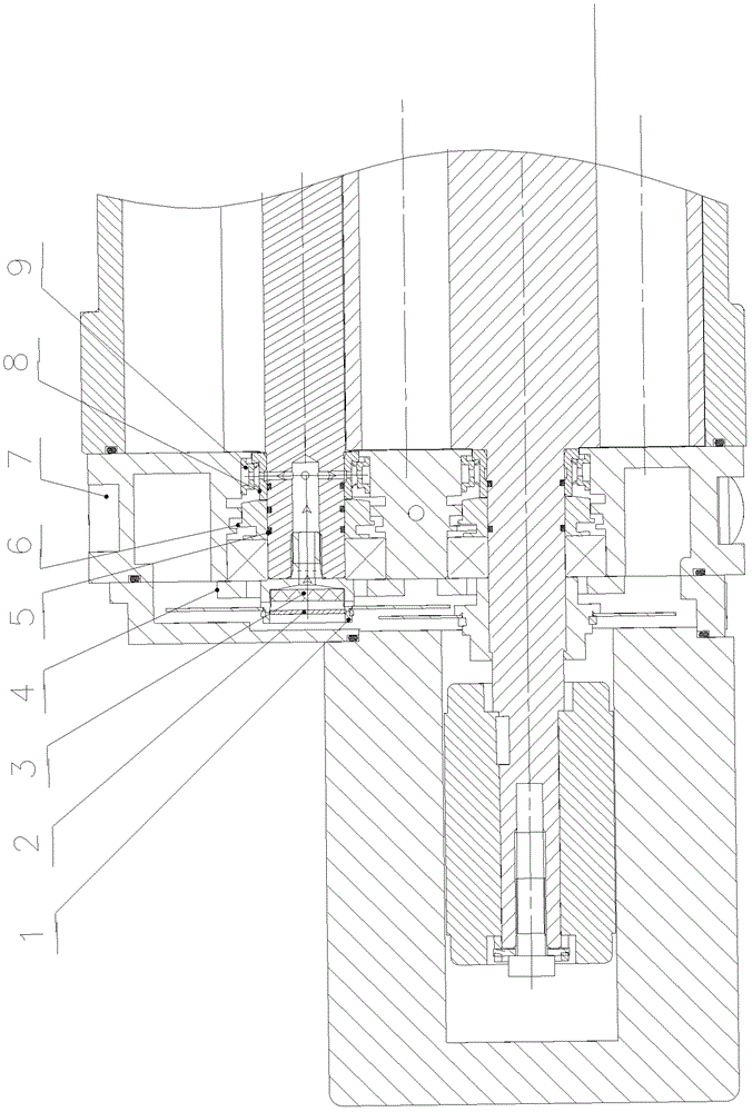
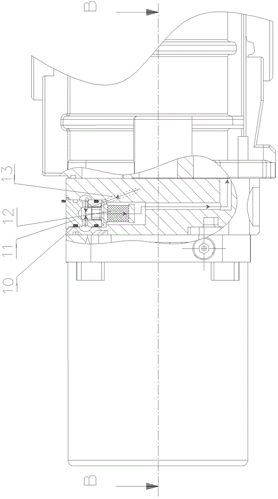
[0025] like figure 1 , figure 2 As shown in the figure, the present invention includes a shaft, a double-lip shaft seal 9, a filter device and an oil-air separation device that penetrate the oil chamber 4, the bearing chamber 7 and the pump chamber in sequence, and the shaft is in the axial direction at the part of the bearing chamber 7 and the oil chamber 4. A blind hole is provided, the filter device is arranged at one end of the blind hole close to the oil cavity 4, and the bearing cavity section of the shaft is radially provided with a through hole communicating with the blind hole; the double-lip shaft seal 9 passes through It is installed in the bearing seat of the bearing cavity 7, and is arranged at the radial through hole of the shaft. There is a ventilation hole in the circumferential direction between the two sealing sheets of the double-lip shaft seal 9. Th...


PUM


Abstract

The invention relates to the field of vacuum pumps, in particular to a vacuum pump seal structure. The vacuum pump seal structure comprises a shaft penetrating through an oil cavity, a bearing cavity and a pump cavity in sequence, double lip shaft seal, a filter device and an oil-gas separation device. A part, in the bearing cavity and the oil cavity, of the shaft is provided with a blind hole along the axial direction, the filter device is arranged at one end, close to the oil cavity, of the blind hole, a bearing cavity section of the shaft is provided with a through hole along the radial direction, and the through hole is communicated with the blind hole. The double lip shaft seal is located inside a bearing seat of the bearing cavity, and a vent hole is formed in the middle of two seal sheets of the double lip shaft seal along the peripheral direction and communicated with the blind hole of the shaft. The oil-gas separation device is located on the upper portion of the bearing cavity, a first air hole and a second air hole are formed in a cavity body of the bearing cavity, one end of the first air hole is communicated with the upper portion of the oil-gas separation device, the other end of the first air hole is communicated with the vent hole in the double lip shaft seal, one end of the second air hole is communicated with the bottom portion of the oil-gas separation device, and the other end of the second air hole is communicated with the pump cavity. The vacuum pump seal structure is good in sealing effect and solves the problem of returning oil to the pump cavity.

Description

technical field [0001] The invention relates to the technical field of vacuum pumps, in particular to a vacuum pump sealing structure. Background technique [0002] Dry mechanical vacuum pump (also referred to as dry mechanical pump) means that the pump can start pumping from atmospheric pressure, and can directly discharge the pumped gas into the atmosphere. There is no oil or other working medium in the pump cavity, and the pump is The ultimate pressure is the same as or close to the mechanical vacuum pump of the oil-sealed vacuum pump. With the rapid development of the semiconductor industry, chemical industry, and thin film industry, the domestic and foreign dry mechanical vacuum pump market continues to grow. Due to the development of these industries, the requirements for the vacuum environment are becoming more and more strict, and higher requirements are placed on the vacuum pump. One is The ultimate vacuum should be as high as possible, and the other is that the va...

Claims


Application Information

Patent Timeline
Patent Type & Authority Patents(China)
IPC IPC(8): F04B39/00F04B39/16
Inventor 张振厚王光玉刘在行
Owner SHENYANG SCI INSTR RES CENT CHINESE ACAD OF SCI
Why Eureka
Try Eureka