Surface plasmon longitudinal field scanning near-field optical microscope device and detection method

A technology of surface plasmon and scanning near-field optics, which is applied in the field of optical sensing and imaging, can solve problems that affect the quality of SPPs light field detection, fail to obtain SPPs light field imaging, and reduce detection reliability, so as to improve reliability and Stability, easy operation, effect of reducing interference

Inactive Publication Date: 2016-01-13
NANKAI UNIV
View PDF9 Cites 0 Cited by
  • Summary
  • Abstract
  • Description
  • Claims
  • Application Information

AI Technical Summary

Problems solved by technology

Due to the surface wave characteristics of SPPs, the electric field strength of SPPs exhibits an exponential decay form in the direction perpendicular to the interface, so traditional optical microscopy methods cannot image them.
[0003] At present, the more common instrument for measuring the near-field distribution is the scanning near-field optical microscope (SNOM), but there are some defects and deficiencies in the near-field detection of surface plasmons by using SNOM: , in general only the transverse component of the light field in the near-field region can be detected
Since the transmitted light can also be effectively coupled to the fiber optic probe of SNOM, the near-field distribution obtained by using SNOM is the superposition of SPPs and transmitted light, which affects the detection quality of SPPs light field to a certain extent.
Especially in the case of high numerical aperture focusing, the intensity of the transmitted light is even greater than that of the generated SPPs, thus greatly reducing the reliability of the detection
Especially in the light field near the focal point, there has not been a perfect SPPs light field imaging

Method used


Image

  • Surface plasmon longitudinal field scanning near-field optical microscope device and detection method
  • Surface plasmon longitudinal field scanning near-field optical microscope device and detection method
  • Surface plasmon longitudinal field scanning near-field optical microscope device and detection method

Examples


Embodiment

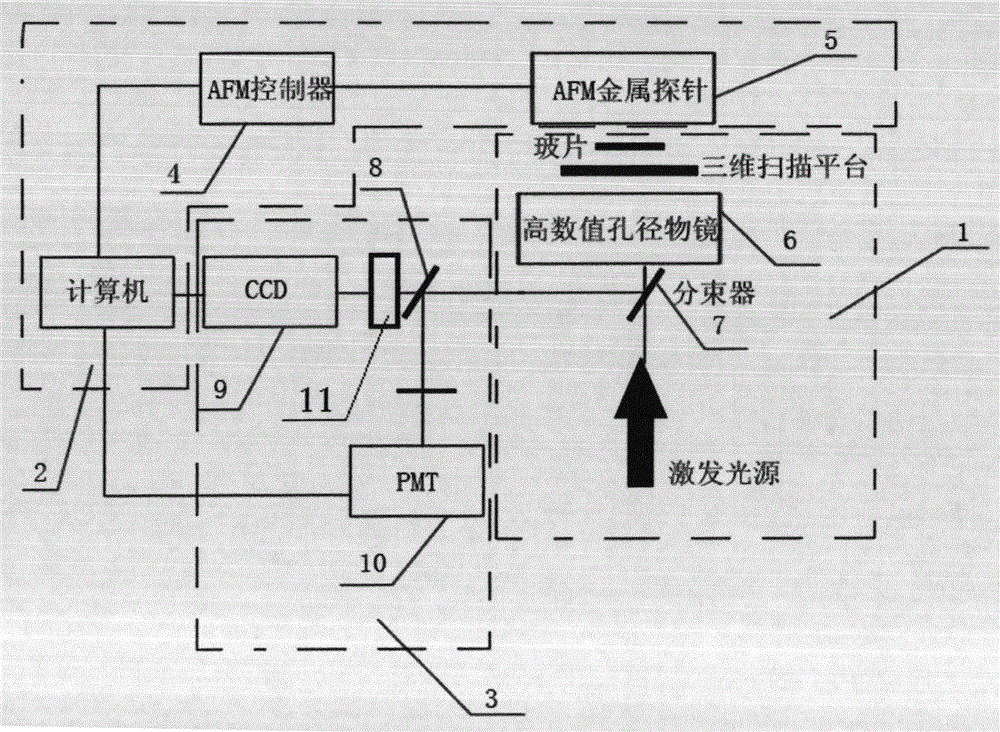
[0027] Example: such as figure 1 , 2 , 3, 4, 5,

[0028] A surface plasmon longitudinal field scanning near-field optical microscope device has a surface plasmon excitation unit 1, a scanning control unit 2 and a detection unit 3. The surface plasmon excitation unit 1 includes: an excitation light source, a first beam splitter 7, a high Numerical aperture objective lens 6, glass slide plated with 45nm silver film, three-dimensional scanning platform; glass slide plated with 45nm silver film is set on the three-dimensional scanning platform, on which Raman molecules are adsorbed by self-assembly; the beam emitted by the excitation light source penetrates The first beam splitter 7 and the high numerical aperture objective lens 6 are irradiated on the glass slide with the Raman molecules adsorbed; the scanning control unit 2 includes: AFM metal probe 5, AFM controller 4, computer; AFM controller 4 controls and connects to AFM Metal probe 5; computer control connected to AFM control...


PUM


Abstract

The invention provides a surface plasma longitudinal field scanning near-field optic microscope device and a detection method. The device is provided with a surface plasma excitation unit (1). After being focused through a high numerical aperture objective lens (6), incident light excites an SPP field on an interface of a metal membrane and air, raman signals and the SPP field interfere each other to form a stationary field of the SPP field around a focus, a scanning control unit (2) can achieve three-dimensional scanning and positioning for an atomic force microscope (AFM) metal probe (5) by means of an AFM controller (4), and a detection unit (3) achieves three-dimensional measurement and analysis for a longitudinal field component of a surface plasma field.

Description

Technical field [0001] The invention belongs to the technical field of optical sensing and imaging for near-field optical detection, and particularly relates to a method and device for detecting a longitudinal field of surface plasma. Background technique [0002] In the prior art, the fine structure and undulation information of an object smaller than the diffraction limit under near-field conditions is closely related to the non-radiative field bound to the surface of the object. On the one hand, the non-radiative field in the near-field region contains detailed information of the object structure ; On the other hand, since the field strength of this field decays exponentially with the distance from the surface, it cannot be detected in the far field, that is, in traditional optical detection technology. This contradiction focuses the core problem of near-field optics on the technology of detecting the non-radiation field bound to the surface of the object, and spreading the no...

Claims


Application Information

Patent Timeline
Patent Type & Authority Patents(China)
IPC IPC(8): G01Q60/18
Inventor 袁小聪杜路平沈军峰朱思伟闵长俊方晖
Owner NANKAI UNIV
Why Eureka
Try Eureka