
Homomorphous wave time difference positioning method based on data base technology

A technology of time difference positioning and database, which is used in beacon systems using ultrasonic/sonic/infrasonic waves, seismic signal processing, etc.

Active Publication Date: 2013-05-15
BC P INC CHINA NAT PETROLEUM CORP +1
View PDF3 Cites 12 Cited by
  • Summary
  • Abstract
  • Description
  • Claims
  • Application Information

AI Technical Summary

Problems solved by technology

If the accuracy of inversion positioning cannot be guaranteed, wrong judgments may be drawn; if the speed of inversion positioning cannot be guaranteed, the real-time performance of microseismic monitoring cannot be guaranteed

Method used


Image

  • Homomorphous wave time difference positioning method based on data base technology
  • Homomorphous wave time difference positioning method based on data base technology
  • Homomorphous wave time difference positioning method based on data base technology

Examples


Embodiment 1

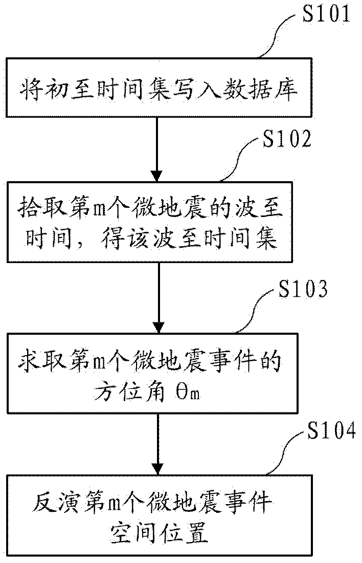
[0056] Embodiment 1 is a P-wave time-difference positioning method based on database technology.

[0057] The P-wave time-difference positioning method according to example embodiments will be specifically described below.

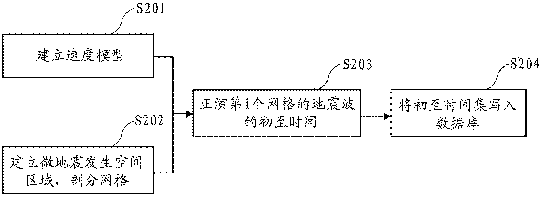
[0058] First, in order to establish the first arrival time database (S101), a fine velocity model V of P waves is established based on well logging data and perforation data P (x, y, z) (S201).

[0059] Then, the microseismic occurrence spatial region and subdivided grid are established (S202).

[0060] In the fracturing construction design, there will be a given fracturing occurrence area. The area is expanded in combination with the seismic horizon and fault characteristics, and a larger microseismic source area is obtained.

[0061] Establish a cuboid space, the cuboid space Volume must include all microseismic space occurrence areas, and calculate the x-direction length of the cuboid space volume Volume as L x , the length in the y direction is L ...


PUM


Abstract

The invention relates to geophysical exploration microseism monitoring technology, in particular to a homomorphous wave time difference positioning method with computational efficiency improved greatly and combined with data base technology and under the condition that computational accuracy is guaranteed. The homomorphous wave time difference positioning method based on the data base technology comprises the following steps that (1) microseism happening space zone is established and grid subdivision is performed; (2) a forward modeling result of P wave or S wave of each grid is written to a data base by ray tracing algorithm; (3) combined with an azimuth angle of an actual microseism happening space, whether an azimuth angle of the i grid volume i (x, y, z) is in a range (theta m-theta', theta m+ theta') determined by the azimuth angle of a microseism event is judged and if the azimuth angle of the i grid is in the given azimuth angle range (theta m-theta', theta m+ theta'), a spatial point volume i (x, y, z, theta m + / - theta') where a microseism can happen is determined; and (4) in a microseism happening space zone volume, optimal seismic focus location search is performed on all grid points volume i (x, y, z, theta m + / -theta') with the azimuth angle located in the (theta m-theta', theta m+ theta') according to a formula.

Description

technical field [0001] The invention relates to a microseismic monitoring technology for geophysical exploration, and more specifically, relates to a time-difference positioning method of isotype waves combined with database technology. Background technique [0002] Microseismic monitoring is a geophysical technology that monitors the impact, effect and underground state of production activities by observing and analyzing small seismic events generated in production activities. The method is to arrange geophones on the ground or in wells during the fracturing process of oil and gas reservoir development to receive microseismic waves (commonly referred to as microseismic events) when artificial fractures are received in formations during fracturing construction. By performing a series of data processing techniques on the received microseismic events (P wave or S wave), the spatial position of artificial fractures is inverted, so as to predict the development trend and spatial...

Claims


Application Information

Patent Timeline
IPC IPC(8): G01V1/28G01S1/72
Inventor 尹陈刘鸿李亚林何光明巫芙蓉陈爱萍巫骏
Owner BC P INC CHINA NAT PETROLEUM CORP
Learn More