

Electronic toll collection system using laser radar in long communication area
An electronic non-stop, lidar technology, applied in instruments, ticketing equipment, etc., can solve the problems of reducing the efficiency of ETC lanes, heavy maintenance workload, and inability to meet the needs of fast passage of vehicles, and achieve the effect of ensuring the success rate of transactions.
- Summary
- Abstract
- Description
- Claims
- Application Information
AI Technical Summary
Problems solved by technology
Method used
Image

Examples
Embodiment 1
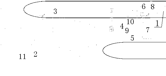
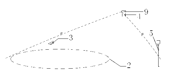
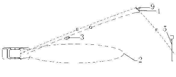
[0033]This embodiment comprises a lane master controller 1, a license plate recognition unit 3, an antenna 4, an electric railing 5, a fee display 6, a drop rod coil 7 and a lane camera 8, and the antenna 4 is projected obliquely downward to form an antenna communication coverage area 2, and the antenna Both sides of the communication coverage area 2 are provided with vehicle isolation devices 11, and the lane master controller 1 is respectively connected with the license plate recognition unit 3, the antenna 4, the electric railing 5, the toll display 6, the drop pole coil 7 and the lane camera 8, and the lane master controls The device 1 is connected with a laser radar 9. Antenna 4 and laser radar 9 are installed on the gantry 10, fee amount display 6 is installed in front of the electric railing 5, drop pole coil 7 is installed in the back of the electric railing 5, lane camera 8 is installed in the rear of the electric railing 5, and the license plate recognition unit 3 foc...
Embodiment 2
[0044] In this example, figure 1 The electric railing 5, the fee display 6, the drop rod coil 7, and the lane camera 8 in the vehicle move toward the direction of the vehicle relative to "embodiment 1". The near end of the antenna communication coverage area 2 is basically flush with the electric railing 5, and the antenna communication coverage area 2 The distance between the proximal end and the electric railing 5 is close to 0 or a negative number, and the others are the same as in "Example 1".
Embodiment 3
[0046] In this example, figure 1 The electric railing 5, the fee amount display 6, the drop pole coil 7, and the lane camera 8 in the vehicle move toward the direction of travel of the vehicle relative to "embodiment 1". The distance between the near end of the communication coverage area 2 and the electric railing 5 increases. In this embodiment, the first vehicle can take out the card at the automatic card issuing machine, or be handled by a toll collector. After completing the operation of taking out the card, collecting fees, or leaving the lane by manual guidance, the system can process the subsequent vehicles.
PUM
| Property | Measurement | Unit |
|---|---|---|
| Length | aaaaa | aaaaa |
Abstract
Description
Claims
Application Information