
Electronic device

A technology for electronic devices and circuit boards, which is applied in the fields of electrical digital data processing, instruments, digital data processing parts, etc., can solve the problems of increasing the cost of material preparation and storage, complicated and unstable processing technology, etc.

Inactive Publication Date: 2013-05-15
INVENTEC CORP
View PDF0 Cites 2 Cited by
  • Summary
  • Abstract
  • Description
  • Claims
  • Application Information

AI Technical Summary

Problems solved by technology

However, this configuration method will reduce the area available for configuring circuits on the main board, and will also cause interference to the configuration of parts on the other side of the main board, and increase the time for the assembly of components on the main board surface, so that the processing technology complication
Furthermore, because copper nails are required for locking, the manufacturer still needs to prepare additional materials, which correspondingly increases the cost of materials preparation and storage
[0004] And when extending one end of the interface module of the tiny peripheral components out of the side of the main board to lock with the casing as a fixed method, since the two ends of the connection port module of the small peripheral components are respectively connected to the main board and the casing, because the overall The mechanism is complex, which will cause assembly tolerances, which will cause problems such as poor contact and instability between components

Method used


Image

  • Electronic device
  • Electronic device
  • Electronic device

Examples


Embodiment Construction

[0026] Below in conjunction with accompanying drawing, structural principle and working principle of the present invention are specifically described:

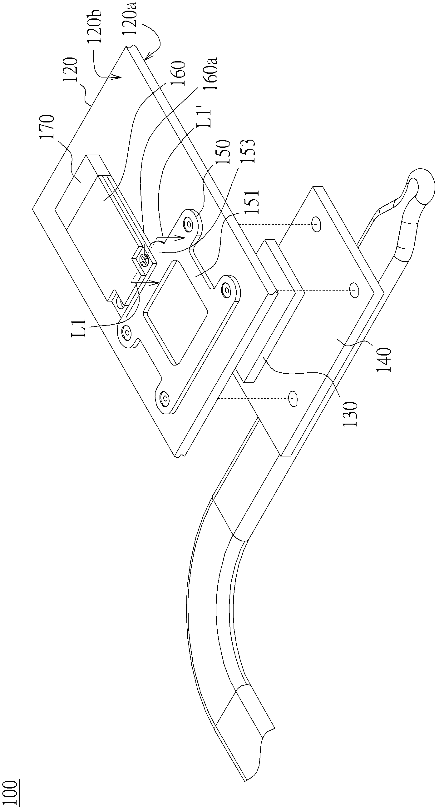
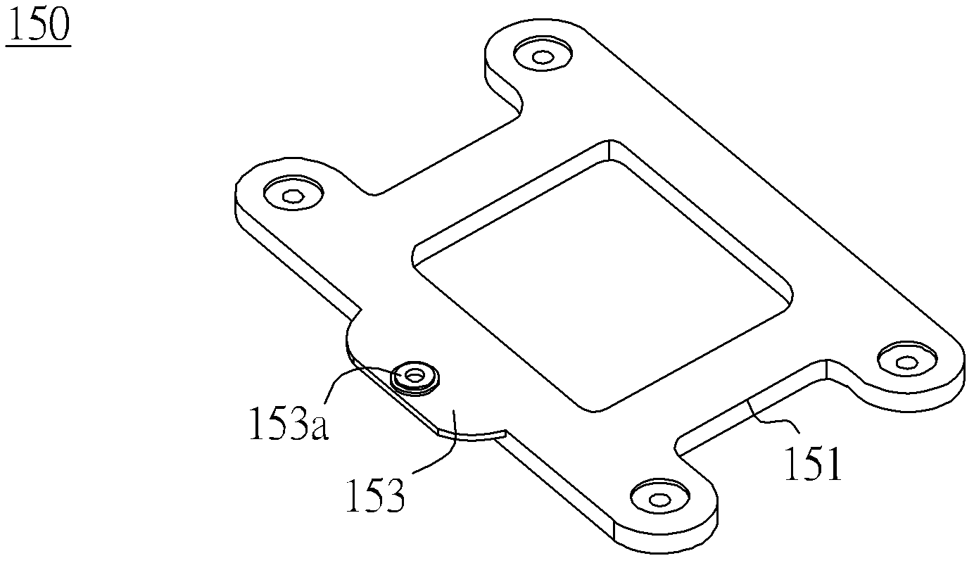
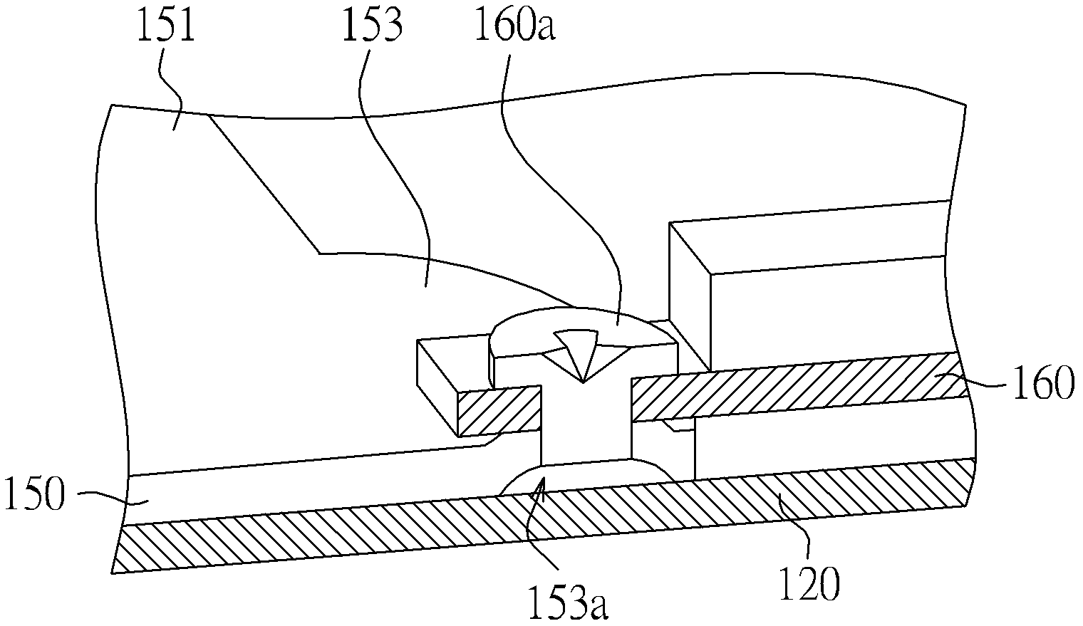
[0027] Please refer to figure 1 , which is a schematic diagram of an electronic device according to an embodiment of the present invention. The electronic device 100 includes a circuit board 120 , a chip 130 , a heat dissipation module 140 , a fixing plate 150 , a function module 160 , and a connector 170 . The circuit board 120 has a first surface 120a and a second surface 120b, and the first surface 120a is opposite to the second surface 120b. The chip 130 is disposed on the first surface 120 a , the heat dissipation module 140 is disposed on the chip 130 , and the fixing plate 150 is disposed on the second surface 120 b corresponding to the chip 130 and is suitable for connecting with the heat dissipation module 140 . One end of the functional module 160 is locked on the fixing plate 150 , the connector 170 is disposed on...


PUM


Abstract

An electronic device comprises a circuit board, a chip, a heat dissipation module, a fixing plate, a functional module and a connector. The circuit board is provided with a first surface and a second surface, the chip is arranged on the first surface, the heat dissipation module is arranged on the chip, and the fixing plate corresponding to the chip is arranged on the second surface and connected with the heat dissipation module. One end of the functional module is fixed on the fixing plate in a locking mode, the connector is arranged on the second surface of the circuit board, and the functional module is in electric connection with the circuit board through the connector.

Description

technical field [0001] The invention relates to an electronic device, and in particular to an electronic device with functional modules. Background technique [0002] Generally speaking, in a notebook computer, the way to fix the Mini peripheral component interconnect module (Mini PCI module) on the main board is to use copper nails to lock into the through holes of the main board, and lock Fixing the micro-peripheral component connection port module on the main board, or extending the other end of the micro peripheral component connection port module from the side of the main board relative to the connector on the main board to lock with the casing. [0003] When locking the micro-peripheral component connector module on the motherboard by using copper nails to lock into the through holes of the motherboard, the motherboard must be punched. However, this configuration method will reduce the area available for configuring circuits on the main board, and will also cause inte...

Claims


Application Information

Patent Timeline
IPC IPC(8): G06F1/20G06F1/16
Inventor 赖昆辉
Owner INVENTEC CORP
Learn More