Loaded power divider

A power divider and coupling cavity technology, which is applied to waveguide-type devices, electrical components, connecting devices, etc., can solve the problems of reduced processing accuracy, high broadband series, and increased volume at the intersection, and achieves high broadband series. Low processing difficulty and small volume

Active Publication Date: 2013-05-15
成都赛纳赛德科技有限公司
View PDF10 Cites 8 Cited by
  • Summary
  • Abstract
  • Description
  • Claims
  • Application Information

AI Technical Summary

Problems solved by technology

[0003] The purpose of the present invention is to overcome a series of problems such as increase in the volume of the intersection and decrease in machining accuracy due to the need for a three-dimensional complex structure for the waveguide crossover and crossover, and provide a waveguide crossover and crossover transmission that can be realized on one plane. Loaded power splitter with high broadband series

Method used


Image

  • Loaded power divider
  • Loaded power divider
  • Loaded power divider

Examples


Embodiment 1

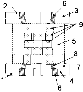
[0025] Such as figure 1 As shown, the loaded power splitter includes a coupling cavity 5, and an input and output terminal connected to the coupling cavity 5, that is, an input terminal 1, an output terminal 2, a coupling terminal 3, and an isolation terminal 4 connected to the coupling cavity 5. The input end 1 and the isolation end 4 are located on the front face of the coupling cavity 5, the coupling end 3 and the output end 2 are located on the rear end face of the coupling cavity 5, and the front end face and the rear end face are two opposite end faces of the coupling cavity. The isolation terminal 4 is located on the right side of the input terminal 1, and the coupling terminal 3 is located on the right side of the output terminal 2. The coupling cavity 5 is provided with columns 9, the columns 9 are arranged in 5 rows along the front-to-back axis of the input end 1, and the columns 9 are arranged in 3 rows along the direction perpendicular to the front-to-back axis of ...

Embodiment 2

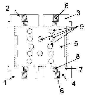
[0032] Such as image 3As shown, the difference from Example 1 is that 12 cylindrical columns are used instead of 12 rectangular columns 9 .


PUM


Abstract

The invention discloses a loaded power divider. The loaded power divider comprises a coupling cavity, an input terminal, an output terminal, a coupling terminal and an isolation terminal, wherein the input terminal, the output terminal, the coupling terminal and the isolation terminal are communicated with the coupling cavity; the input terminal and the isolation terminal are located at a front end face of the coupling cavity, the coupling terminal and the output terminal are located at a rear end face of the coupling cavity, the isolation terminal is located at the right side of the input terminal, and the coupling terminal is located at the right side of the output terminal; and columnar bodies are arranged in the coupling cavity, are arranged into at least three rows along the direction of the front-rear axis of the input terminal, are arranged into at least two columns along the direction vertical to the front-rear axis of the input terminal, and are connected with an upper internal wall or lower internal wall of the coupling cavity. The power divider disclosed by the invention has over 59% relative operating bandwidth and has the characteristics of simple structure, small volume and low processing difficulty. The loaded power divider can be widely applied to the military and civilian fields of antenna arrays, phased-array radar, power synthesis, missile guidance, communications and the like.

Description

technical field [0001] The invention relates to a power divider. Specifically, it relates to a broadband two-way power splitter loaded with multiple columns, that is, a loaded power splitter. Background technique [0002] The power splitter is a common component in modern microwave communication and military electronic systems. Due to its high power capacity and low insertion loss, waveguide power splitters are widely used. The two-way waveguide power splitter can be used alone, or can be connected in series to form a multi-way power splitting network, which is used in the fields of phased array radar, antenna array, and power combination. The existing two-way waveguide power splitter mainly includes E-plane T-shaped branch, H-plane T-shaped branch, waveguide magic T, H-plane waveguide crack bridge, etc. Among them, due to the low isolation between the two output terminals of the first two devices, the mismatch of any output port will seriously affect the amplitude and ph...

Claims


Application Information

Patent Timeline
Patent Type & Authority Applications(China)
IPC IPC(8): H01P5/16
Inventor 王清源谭宜成王聪玲
Owner 成都赛纳赛德科技有限公司
Why Eureka
Try Eureka